

Building a DIY 5.1 Audio Video Receiver – Part 4
As I mentioned in my last post, after measuring the frequency response and testing the TDA 7498, I decided to buy one more. The board I bought earlier did not have the right LC filter for a 6 ohms speaker. It was designed for 8 ohms speaker. So I decided to use that board for my rear surround speakers which were also 6 ohms. However, it is fine to have a slightly poor quality amp for the rarely used rear speakers.
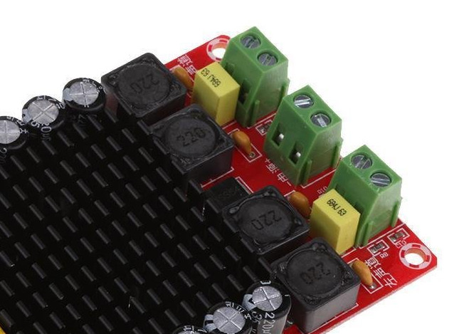
Then I set out searching for another TDA 7498 speaker amplifier board with a 680 nF capacitor RC filter. I found one on amazon for Rs. 1,200 at the time of purchase. This board is slightly more expensive than the last one, but it has a 684 nF capacitor. Which is the right low pass filter configuration for my 6 ohm front speakers.
Power source and speaker connections
Like before, I did not buy a power source because I had another unused laptop charger. The difference with this board from the earlier one was that there is no barrel connector for power. Instead, this manufacturer went with a 2 pin screw terminals. So I had to cut my charger cable, splice the positive and negative wires and connect them on the screw terminal. A bit more effort, but it is fine.
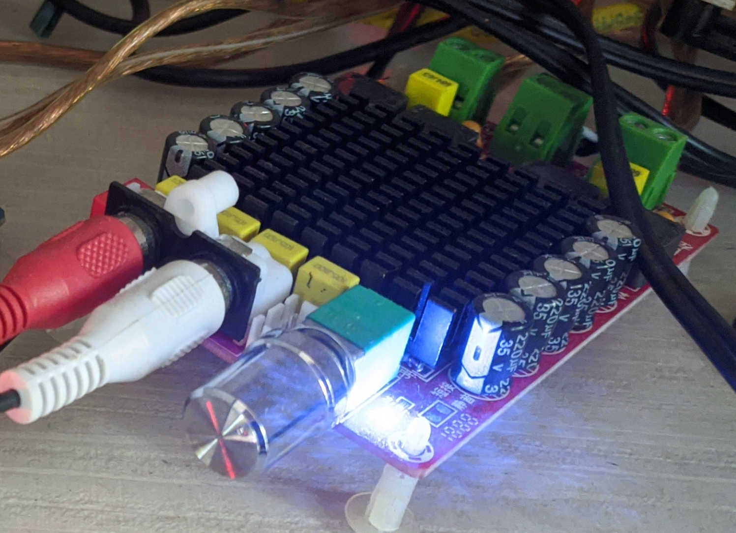
I also connected my front speaker wires. As usual I connected my phone to the board via RCA cables. Time for some audio test.
Sound test
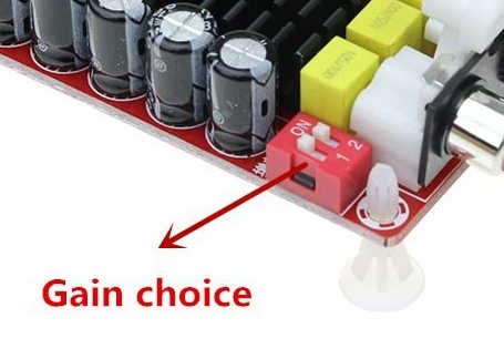
Again the audio quality was really good. It performed similar to the previous board. However one thing I noticed was that the sound was coming out lower than the previous one. Thankfully these board come with dip switches to control gain. So I increased the gain and using the volume control I balanced the front speaker volume levels to the back speaker volume.
I ran the usual battery of tests to make sure everything was in order. The output response was good. The heat sink was doing a perfect job and was just warm to touch. And why not, since the power delivery to the board was only 18.5V and 65W while it is really capable of 200W. The RC filter was also just warm to touch and was able to dissipate the heat generated while filtering the switching frequency. There is also no DC offset at the output stage.
Conclusion
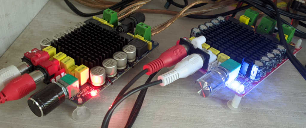
The new board has a much better low pass filter and the heat sink is screwed to the board properly unlike the old one. Together with these boards I now have a 4.0 speaker setup. My 4 Andrew Jones speakers already sound really good but why stop here? I wanted to bring up the sub woofer next to give some oomph to the music. That story in the next part.
You can read all the parts in this DIY series by following the links below --
Part 1, Part 2, Part 3, Part 4, Part 5, Part 6, Part 7