

Building a DIY 5.1 Audio Video Receiver – Part 3
The TDA7498 class D amplifier board that I purchased to power my front speakers was working great. The audio quality is at par with what my Pioneer 5.1 AVR delivered using class AB amplifier. I could not tell the difference in audio quality. None the less, I wanted to make sure the quality is really as good as my ears led me to believe. Enter a function generator and oscilloscope to make sure the frequency response is satisfactory over the range of audible frequencies (20 Hz to 20 kHz).
If you don't happen to know, a class D amplifier uses a very high frequency signal to amplify audio signal. It works on the principle of PWM (pulse width modulation). Which means we need a low pass filter to remove high frequency PWM signals at the output stage. The quality of the audio depends on the output LC filter.

Measuring the frequency response
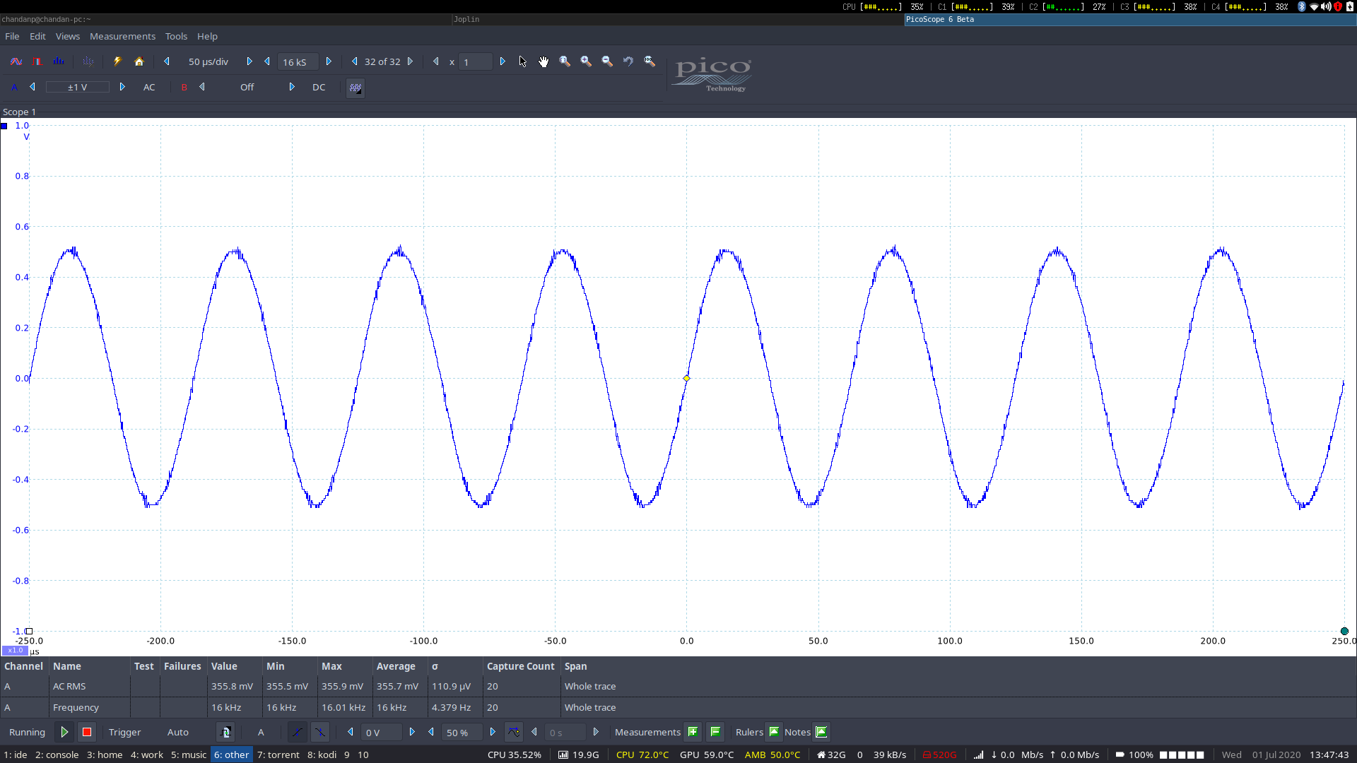
So like I said, I need to make sure the frequency response and the LC filter of the board are good. First lets start with the frequency response. I have an old PicoScope 2205 oscilloscope which I purchased way back in 2011 to take the measurements. It also has the frequency generator function. I took samples at various frequencies and the output was clean and as per the manufacturer's data sheet.

The output is flat at most frequencies and falls off a bit at the lows and highs. Not a problem with the lows because I will add a sub-woofer to take care of those frequencies. The highs are also not a problem for my old ears, because I could not hear anything beyond 15.5 kHz.
The hearing experiment
I learned an interesting fact during this process. While measuring the board's response, I set the frequency generator at 16 kHz. I can see the signal in my oscilloscope but I could not hear it. I was wondering if my speakers were not delivering the sound. So I kept increasing the volume. My daughter who was in the same room closed her ears and was asking what is that high pitch noise? Only then did I realize that the board nor the speakers were at fault. It was my ears which are not picking anything higher than 16 kHz!
Then the whole family played a fun game with the frequency generator. We tried to find out what our hearing limits were. I would select a frequency and randomly turn on or off the function generator. The person being tested should be able to detect when the speaker made a noise. No wonder at all, my daughter won the game by a good margin. Tells you how good a child's senses are and how our senses deteriorate as we age and abuse them.
Low pass filter
The next part was to check if there are any artifacts in the output after the low pass filter. The cut-off frequency of the filter should be more than 25 kHz and much less than the switching frequency. The output looked fine to me.
The data sheet calls for a 680 nF capacitor with a 22 uH inductor to make the LC filter for a 6 ohm speaker.
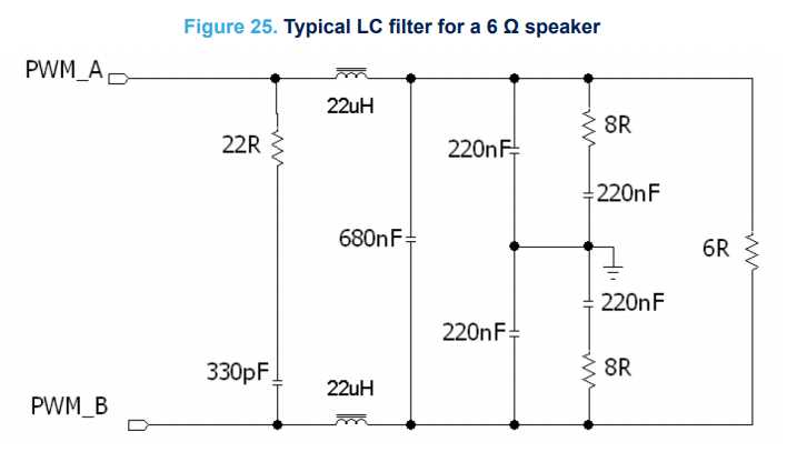
But I noticed that the board uses a 470 nF capacitor which is the configuration for an 8 ohm speaker. It is slightly off, so the filtering will slightly suffer. I should have checked the data sheet before making the purchase.

Build quality
Finally coming to the build quality of the board, it is adequate but not great. The board itself is sturdy and all the solders and components look fine. However, the heat sink on the board is just glued on top of the TDA7498 IC. No screws have been used to fasten it to the board. As a result, the heat sink came off when I was fiddling with the board. I had to tie it down with some wire wrapping around it.
The good part is that even at the loudest output that my ears could handle, the heat sink did not get hot. It was just warm. The filters which eliminate the switching frequencies were also just warm to the touch. No heat issues at all with the board but I wish it came with a heat sink that is properly fastened.
Conclusion
In the end, I am very satisfied with the board. The only issues I found were the LC filter and heat sink. The experiment of building my own 5.1 amplifier is going well. So I decided to add another 2 channel board to drive my 2 rear surround speakers. More on that in the next post.
You can read all the parts in this DIY series by following the links below --
Part 1, Part 2, Part 3, Part 4, Part 5, Part 6, Part 7