

Building a DIY 5.1 Audio Video Receiver – Part 6
In the last post I mentioned that I was looking for a crossover board. The one that I purchased is putting out a huge DC bias and I was not comfortable using it on my sub woofer. Wondering if it is a problem with the particular unit that I got, I ordered a replacement. Unfortunately, even the replacement has the same signature output. So I decided to do something about it myself.
AC coupling capacitor
For those of you who have done electrical engineering might recognize that adding a capacitor in series with the load will block DC offset. This capacitor is usually called the AC coupling capacitor. It couples the input AC signal with output but eliminates DC.
Now to figure out the right value of the capacitor I need to know the input impedance of my sub woofer. I searched for Pioneer S51-W service manual and found one. According to it, the input signal goes to a buffer IC502.
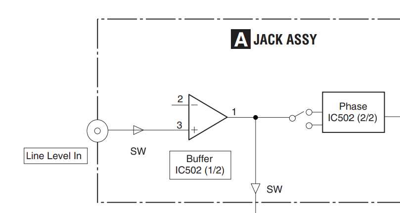
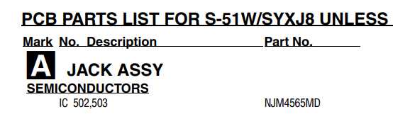
Now to find out the part number of IC502 which I found out to be NJM4565MD after searching through the service manual.
Looking up the datasheet for NJM4565MD, I found the minimum input impedance to be 0.3 M Ohms.
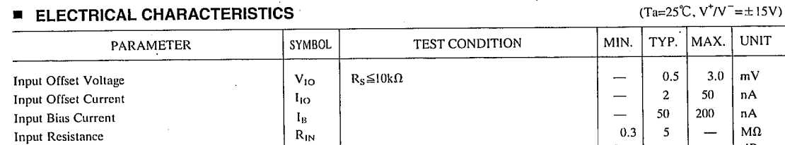
All I need to do is find the value of the capacitor using the input impedance of 300 K Ohms. However when I checked with my multimeter it came out to 50 K Ohms, so decided to go with that value. I found a nifty coupling capacitor calculator online which tells me that I need a 1.59 uF capacitor. I had only 10 uF caps though and even those I had only 4. So I put all 4 of them in series to get 2.5 uF effective capacitance.
Audio test
I finally dared to connect the output from the capacitor to my sub woofer. Played a few audio clips with deep bass and everything was working well. Tested a few movies and music files and everything was working perfectly. I played around with the cutoff frequency selector on the board until I felt that the sub woofer was nicely complementing my front speakers. The cut off frequency I liked was around the 83 Hz mark. The sound was amazing!
Conclusion
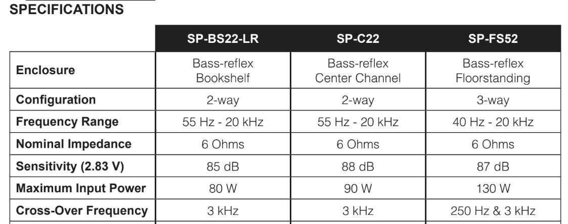
I finally have a proper surround sound system. Still have to bring up the center speaker, but that is a story for another day. The crossover board was doing a pretty good job I should say except for the DC bias. I left a review on amazon describing the issue and noted that a coupling capacitor needs to be added. Now you may be wondering why I don't have cross-overs done for the rest of the speakers. Well, my speakers have in-built cross-overs. In fact my floor standing front speakers have 3-way crossover.
You can read all the parts in this DIY series by following the links below --
Part 1, Part 2, Part 3, Part 4, Part 5, Part 6, Part 7