

Building a DIY 5.1 Audio Video Receiver – Part 5
So far I have finished bringing up 4 of my 5.1 speakers in my DIY 5.1 AVR project. If you missed, check out part 1, part 2, part 3 and part 4 of the series. Next I wanted to bring up my sub-woofer. Since I have an active sub-woofer, I did not need any amplifiers to drive it. I just need to connect the output signal from my audio source directly to the sub-woofer input. But there is a catch. If you connect the audio source directly to the sub-woofer, the sub would be wasting a lot of energy which may heat up the driver and may damage it. Moreover driving the sub with all the frequencies will give boomy muddled up sound. So we need a low pass filter or a crossover.
Why do you need a crossover?
Why would sending a direct audio signal waste energy in a sub-woofer? The reason is the specifications of the sub-woofer. They are designed to deliver output in a narrow low frequency range. For example my sub is designed for a frequency response in the range of 26Hz-900Hz. So all other frequencies that are fed to the speaker are just generating heat in the coil because they cannot be dissipated via the speaker.
So what you need is a low pass filter to remove the frequencies that the speaker cannot handle. That is where a crossover comes in. A crossover splits the input audio signal into multiple bands of frequencies. For example a 2-way crossover will split the frequencies into 2 bands. One for low frequencies which a large speaker can handle and another band of high frequencies that a smaller speaker can handle.
Crossover with frequency selector
I wanted to go with a crossover that has a frequency selector for the AVR that I am building. You see, most of the active low pass filter boards I was looking at have a predefined crossover point like 50 Hz. But I wanted a board that can do crossover at multiple points so I can adjust the sound signature according to my liking. After much searching I finally found the Rackeys Subwoofer Filter Bass Board to fit my needs.
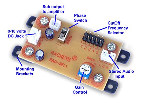
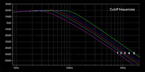
This board has a cut-off frequency selector that I can change to my liking. When I had my Pioneer AVR (before it burned due to power surge), there was a setting to change the crossover point. I could choose from 50 Hz, 80 Hz, 150 Hz and 200 Hz options. If I remember correctly I used the 80 Hz crossover point. I was excited with this board because it offered cut-off points at 40Hz, 58Hz, 70Hz, 86Hz and 117Hz.
Power source and signal test
As usual I have to test the signal before connecting it directly to the sub-woofer. But first I needed a power source. The board can operate over a wide range of voltages from 9V to 18V DC. As usual, I have a power adapter that can deliver 12V lying in my electronics mess. This is the advantage of hobby electronic projects. You always have things lying around in the house :).
After providing an input audio signal via my phone, I check the output signal using my trusty oscilloscope. The signal is clean and does taper off at the specified frequencies as per the data sheet. But I noticed a problem. The output as a DC bias of 6V which is half the voltage I was supplying!
Conclusion
I did not know if my sub-woofer can handle a DC offset in the signal. A DC voltage without filtering can harm a speaker. It basically drives the cone of a speaker in one direction constantly, wasting energy and also heating up the coil. I read through all the manuals for my sub-woofer but could not find out if there is a DC filter in the circuit for sure. I did not want to find out by connecting the output signal to my sub and burn it. Since I was not sure if it is a problem with this particular board I decided to opt for a replacement from Amazon. What happened next in my next post.
You can read all the parts in this DIY series by following the links below --
Part 1, Part 2, Part 3, Part 4, Part 5, Part 6, Part 7