

Drip Irrigation Control System v4.0 – Software
This is a continuation of my previous post on control system v4.0. In that post I wrote about the hardware. Now I will talk about the software. If you have been following my drip irrigation control system design, you know that I switched from Arduino to ESP8266. It took some time for me learn about the new board, but it is very similar to Arduino when it comes to programming it.
Previously I used to use Arduino IDE, but lately I switched to Visual Studio Code with Platform IO plugin. This combination is quite powerful. Now I can configure build scripts and organize the project to my heart's content. I would highly suggest Platform IO for any project that is more than a few lines of code.
Software
You have seen the hardware design already. So now for the software. I can't copy paste all the code here because that will be a lot. Instead I will show some snippets. If you need the code, check out my github repo. If you rather just watch a video of the software design and overview, just scroll to the bottom of the page.
void setup(void) {
  Serial.begin(115200);
  led.setup();
  led.turnOn();
  lcd.setup();

  lcd.showMessage("Setting up OTA", OTA_HOSTNAME);
  ota.setup(OTA_HOSTNAME, OTA_PASSWORD);

  lcd.showMessage("Connecting to", WIFI_SSID);
  wifi.connect(WIFI_SSID, WIFI_PASSWORD);

  lcd.showMessage("Setting mDNS", HOSTNAME);
  setupFailed = !mdns.setup(HOSTNAME);
  if (!setupFailed) {
    setupFailed = !automation.setup(&lcd, wifi.getIp());
  }

  if (setupFailed) {
    led.blink(300, 300);
  } else {
    led.blink(10, 1000);
    lcd.showMessage("Ready", "");
  }
}
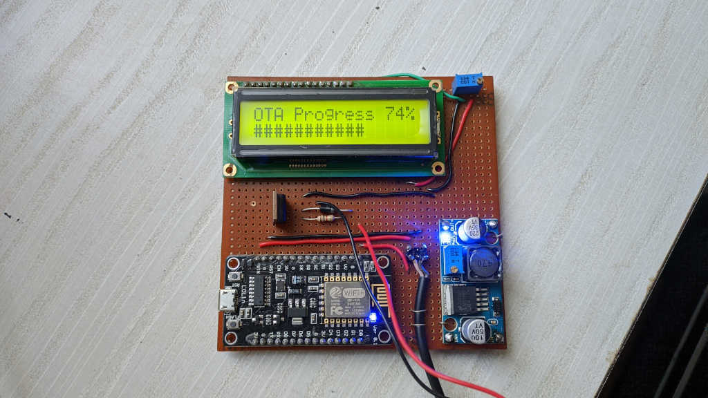
LED, LCD and OTA setup
The first thing the code does is setup LCD and LED. ESP8266 has an in-built LED. So I use it to blink the LED at different rates to indicate various states. For example, blinking on/off for 300 ms indicates error. When everything is working well, the LED is on for 10 ms and off for 1000 ms.
One of the best features of ESP8266 is that fact that it can be programmed over the air (OTA). So anytime I need to change the code, all I need to do is build the binary and update the device over the air. No need for USB connection. All I need is the device to be connected to the router.
void setup(const char* hostname, const char* password) {
  ArduinoOTA.setHostname(hostname);
  ArduinoOTA.setPassword(password);

  ArduinoOTA.onStart([this]() {
    led->blink(300, 300);
    Serial.println("[OTA] Started");
    lcd->showMessage("OTA Started", "");
    SPIFFS.end();
    busy = true;
  });

  ArduinoOTA.onEnd([this]() {
    Serial.println("\n[OTA] Ended");
    SPIFFS.begin();
    busy = false;
  });

  ArduinoOTA.onProgress([this](unsigned int progress, unsigned int total) {
    led->update();
    unsigned int percent = (progress / (total / 100));
    Serial.printf("[OTA] Progress: %u%%\r", percent);
    // Skipping some lines here for brevity...
    lcd->showMessage(line1.c_str(), line2);
  });

  ArduinoOTA.onError([this](ota_error_t error) {
    // Skipping some lines here for brevity...
    lcd->showMessage("OTA Error " + error, errorMessage);
    Serial.println(errorMessage);
    busy = false;
  });

  ArduinoOTA.begin();
  Serial.println("[OTA] Service ready");
}

void handle() {
  ArduinoOTA.handle();
}
Connecting to WiFi and setting up mDNS
The next step is to connect to WiFi. I used hard-coded access point and password to connect to my home WiFi. Then I setup mDNS so I can access the device using a name instead of IP Address. Then, I can access them as sprinkler-right.local, sprinkler-left.local and sprinkler-terrace.local.
$ avahi-browse -all | grep sprinkler
wlp1s0 IPv4 sprinkler-terrace _arduino._tcp local
wlp1s0 IPv4 sprinkler-left _arduino._tcp local
wlp1s0 IPv4 sprinkler-right _arduino._tcp local
wlp1s0 IPv4 sprinkler-terrace _sprinkler._udp local
wlp1s0 IPv4 sprinkler-left _sprinkler._udp local
wlp1s0 IPv4 sprinkler-right _sprinkler._udp local

$ ping sprinkler-left.local
PING sprinkler-left.local (192.168.0.71) 56(84) bytes of data.
64 bytes from sprinkler-left.local (192.168.0.71): icmp_seq=1 ttl=255 time=258 ms
64 bytes from sprinkler-left.local (192.168.0.71): icmp_seq=2 ttl=255 time=377 ms
64 bytes from sprinkler-left.local (192.168.0.71): icmp_seq=3 ttl=255 time=62.3 ms
NTP
To keep track of the time, there is already a RTC on the device. The only problem? It does not have a battery backup. So when there is no power, the time resets to Unix Epoch (1970/01/01 00:00:00). To get over this problem, I use NTP service to fetch the current time and keep track of time that way. Another problem I noticed from my experience with other Arduino projects is that the RTC clock is not accurate. It keeps drifting. For example if the current time is 10:00 and I set it up that way. After a few days, the time will have drifted to 10:02 or something. So with ESP8266 I update RTC every few minutes to fix the drift.
void init() {
  if (initialized) {
    return;
  }
  unsigned long currentMillis = millis();
  if (currentMillis - lastDnsLookup < DNS_LOOKUP_INTERVAL) {
    return;
  }
  lastDnsLookup = currentMillis;

  Serial.println("[NTP] DNS lookup started");
  if (!WiFi.hostByName(NTPServerName,timeServerIP)) {
    Serial.println("[NTP] DNS lookup failed");
  } else {
    Serial.print("[NTP] Time server IP: ");
    Serial.println(timeServerIP);
    sendNTPpacket(timeServerIP);
    initialized = true;
  }
}

void sync() {
  if (!initialized) {
    return;
  }

  unsigned long currentMillis = millis();
  if (currentMillis - lastNtpRequest > UPDATE_INTERVAL) {
    sendNTPpacket(timeServerIP);
  }

  // We've sent an UDP request but never got a response, try again
  if (lastNtpRequest - lastNtpResponse > 0 &&
      lastNtpRequest - lastNtpResponse < UPDATE_INTERVAL &&
      currentMillis - lastNtpRequest > FAILED_UDP_TIME) {
    sendNTPpacket(timeServerIP);
  }

  uint32_t time = getNtpTime();
  if (time) {
    unixTime = time;
    Serial.print("[NTP] Response: ");
    Serial.println(unixTime);
    lastNtpResponse = currentMillis;
  }
}
SPIFFS
Another useful feature of ESP8266 is there is a dedicated file system space. It can be used to store web pages. Since the board can also run a web server, it can serve the pages from the file system. The best part is that you can upload files into this space over the air just like the code. So you can update your web frontend independently of the code running on the device. All over the air! SPIFFS is a flash file system intended for SPI (Serial Peripheral Interface) NOR embedded devices.
EEPROM
Finally there is also some EEPROM space to store configuration information. This is where I store the schedules for the drip irrigation. Once a schedule is added or removed, the information is stored here, so we know the schedule even after a reboot.
void loadSchedule() {
  int appVersion = EEPROM.read(EEPROM_APP_VERSION_LOCATION);
  if (appVersion == APP_VERSION) {
    int numSchedules = EEPROM.read(EEPROM_SCHEDULE_COUNT_LOCATION);
    for (int i = 0; i < numSchedules; i++) {
      schedules.add(new Schedule(
        EEPROM_SCHEDULE_START_LOCATION + i * EEPROM_SCHEDULE_SPACE
      ));
    }
  } else {
    // Version has changed. Clear everything
    EEPROM.write(EEPROM_APP_VERSION_LOCATION, APP_VERSION);
    EEPROM.write(EEPROM_SCHEDULE_COUNT_LOCATION, 0);
    EEPROM.commit();
  }
}

void saveSchedule(MyLinkedList<String>* args) {
  for (int i = 0; i < args->size(); i++) {
    Schedule::save(args->get(i),
      EEPROM_SCHEDULE_START_LOCATION + i * EEPROM_SCHEDULE_SPACE
    );
  }
  EEPROM.write(EEPROM_SCHEDULE_COUNT_LOCATION, args->size());
  EEPROM.commit();
  loadSchedule();
  sendScheduleInfoToClients();
}
The other stuff
Beyond this, there is the basic logic that turns on the pin D1 high when it is time to turn on the sprinkler. When the pin goes high, it drives the power transistor into saturation and opens the solenoid valve which lets the water flow. There is also some code to run a web server and a web socket server which I will cover in the next post since this is already pretty long.
In the meantime enjoy a quick video of the software design.