

Drip Irrigation Control System v4.0 - Hardware
As promised, I started upgrading my drip irrigation control system with v4.0 design and software. If you read my last update on the control system, you know that there are two things that I wanted to add to it. One was a way to access the system via internet, so I don't need to physically configure it. And the other was to add a humidity sensor. I finally worked on the first upgrade. Now my control system is accessible over the net (currently limited to my home network). However, I had to make a few hardware design changes. I replaced Arduino with ESP8266. The why and how follows.
Hardware changes
While Arduino was a perfect choice for a drip irrigation, it lacked the features that I required for a v4 design. I could add a WiFi module, but why bother when there is a very affordable board which comes with WiFi built in? Enter ESP8266, which could be programmed just like the Arduino.
The advantages of having built in WiFi are many. For instance, now I don't need a RTC (real time clock) module DS1307 which I used in my earlier design to track time. I could just query one of the NTP (Network Time Protocol) servers for the current time. Another advantage is that I can program the board over the air. No need for a USB cable. I can even run a Web Server on the board. That way I can have a nice frontend to monitor and configure the system.
New Design
Without further ado, here is the new design.
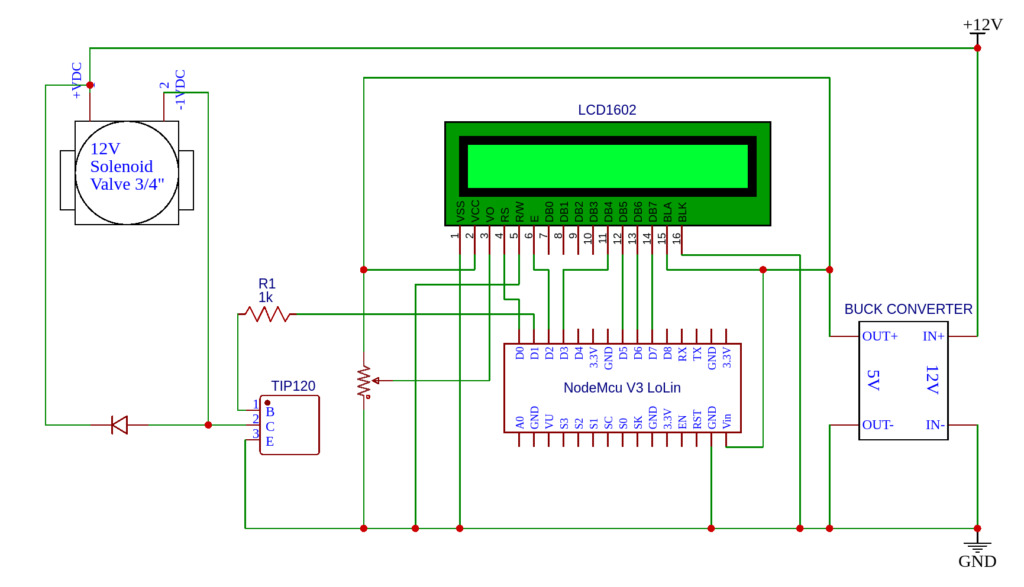
The first thing you will notice from the previous design is that the Arduino is now replaced by NodeMCU. NodeMCU is a development board with ESP8266. I am using LoLin v3 version. As before the board is connected to LCD to display basic status information. Pin D2 is connected to the solenoid valve via the power transistor TIP120. The valve runs on 12VDC while the LCD needs 5VDC. So I also used a buck converter to convert 12VDC to 5VDC. There is also a free wheeling diode and base current limiting resistor to protect the transistor.
You can see my soldering prowess (or the lack there of) in the board that I built (pictures below).
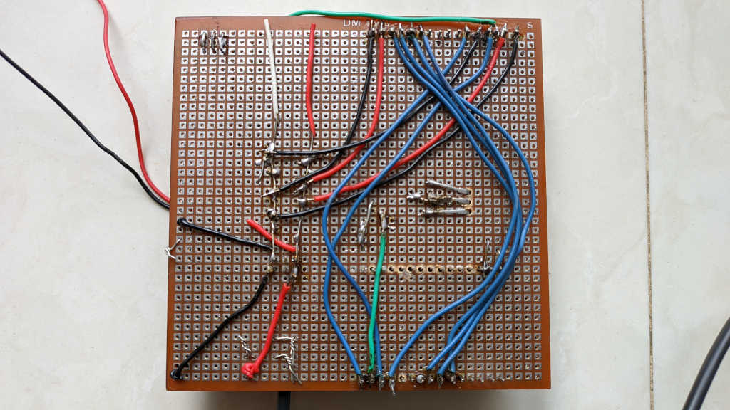

The NodeMCU board is in the bottom left hand corner. The buck converter is on the bottom right. The black wire between those two is the 12VDC line coming from a power adapter. The 12V is directly used in the TIP120 transistor that sits in the middle of the board. Finally there is the LCD display up top along with a pot on the right to adjust the contrast. This PCB then goes into an enclosure so no one can see the mess :).
Since this post is already too long, I will write about the software part in the next post. In the meantime enjoy the demo of the app in the youtube video below.