

Drip Irrigation Control System v2.0 and v3.0
In one of my previous post, I wrote about my drip irrigation control system. But there were a few problems with it. In the process of rectifying them, I built v2.0 and v3.0 control systems. And to think people were asking if I was getting bored in retirement or if I wanted to get back to work :). Why? I love what I do now and it occupies me completely.
The first problem with v1.0 happened to be with the way it was designed. The drips starts as soon as the device is turned on. So if there is a power outage then the board would switch off. Then when the power came back, it will start the drips immediately and will continue dripping everyday at the same time (after the 24 hour cycle). If the power came back in the afternoon, the drips will start then, which was not ideal. Although I never faced this problem because I have UPS that can power the house for 8 hours straight, I did not like the fact that there is this possibility. This led me to build a better version I called v2.0.
The idea was to add a real time clock (RTC) to the Arduino board so I can keep track of what time it is and only turn on the drips if it was evening or morning. I decided to go with the DS1307 IC. It comes with a 3V cell which will keep the clock running even if there is a power failure. The replaceable battery lasts for 10 years, so I wouldn't have to worry about it. The new circuit diagram with DS1307 is as follows.
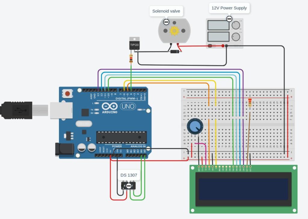
In case the image is too small, here are the connections in text format
 //  Arduino         LCD
 // -------------------------
 //  GND -----+      1 (VSS)
 //  +5V      |      2 (VCC)
 //  +5V --- POT --- 3 (V0)
 //  5               4 (RS)
 //  GND             5 (RW)
 //  6               6 (E)
 //  10              11
 //  11              12
 //  12              13
 //  13              14
 //  +5              15
 //  GND             16
 //
 //
 //  Arduino         RTC
 // -------------------------
 //  A5              SCL
 //  A4              SDA
 //  +5              VCC
 //  GND             GND
 //
 //
 //  Arduino         TIP 120
 // -------------------------
 //  4  ------- 1K ----- 1 (B)
 //
 //        +- Valve -+
 //  +12 --|         |-- 2 (C)
 //        +- Diode -+
 //
 //  GND                 3 (E)
I have updated the Arduino code to use DS1307 to track the time and only start drips at 6 pm everyday. I later changed the code to start at 8 am and at 6 pm in the summer. As you can see from the picture below, the v2.0 also got an enclosure.
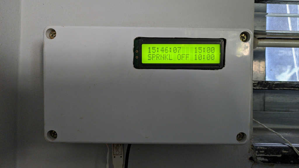
The time being shown on the top left corner of the LCD is the current time in 24 hour format. The top right and bottom right corners display the morning and evening drip duration which also count down when the drips are on. The status SPRNKL OFF indicates that the drips are off currently. That changes to ON at the specified time as written in the code.
Another design change in v2.0 is that instead of using an AC to DC converter circuit, I used a USB charger to power the board and another 12 V DC adapter for driving the solenoid valve. I did this for 2 reasons. One, I got a nice 220V AC shock while I was fiddling with the board. I was stupid enough to not cut the circuit breaker, because I just needed to do small fix ;). I guess while connecting a wire, one of my fingers touched the live wire. The throbbing hand feels funny. By the way, this is not the first time I got an electric shock (and perhaps will not be the last either), so don't worry. The other reason was I did not want to open the enclosure each time I wanted to program the board. With a USB charger, all I need to do is unplug the USB from the power adapter and plug in to my computer to flash the new code on to the board. So that worked like a charm. Note that I still had a lot of hard coded constants in the code like the time of drips, how long the drip should run and how many times in a day the drip should work (once in winter and twice in summer). So I need to flash new code once in a while.

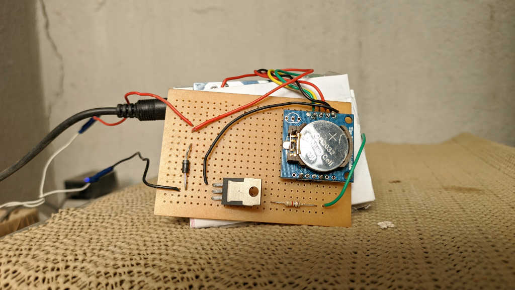
Job done? Nope. I was still not satisfied with this design either. As I mentioned before, there were too many constants in the code and every time I need to change the time or duration, I have to reprogram. At least it is better than v1.0 because I don't have to open the enclosure to reprogram. Still, a programmable board would have been nice. So I made a few more changes and called it v3.0. Thankfully the DS1307 chip I used in v2.0 has a small 56 byte battery-backed, nonvolatile memory which can store data even when the power if off. Great! All I have to do is store the following data
- How many times to start drip in a day (1 or 2 times)
- Morning drip time
- Morning drip duration
- Evening drip time
- Evening drip duration
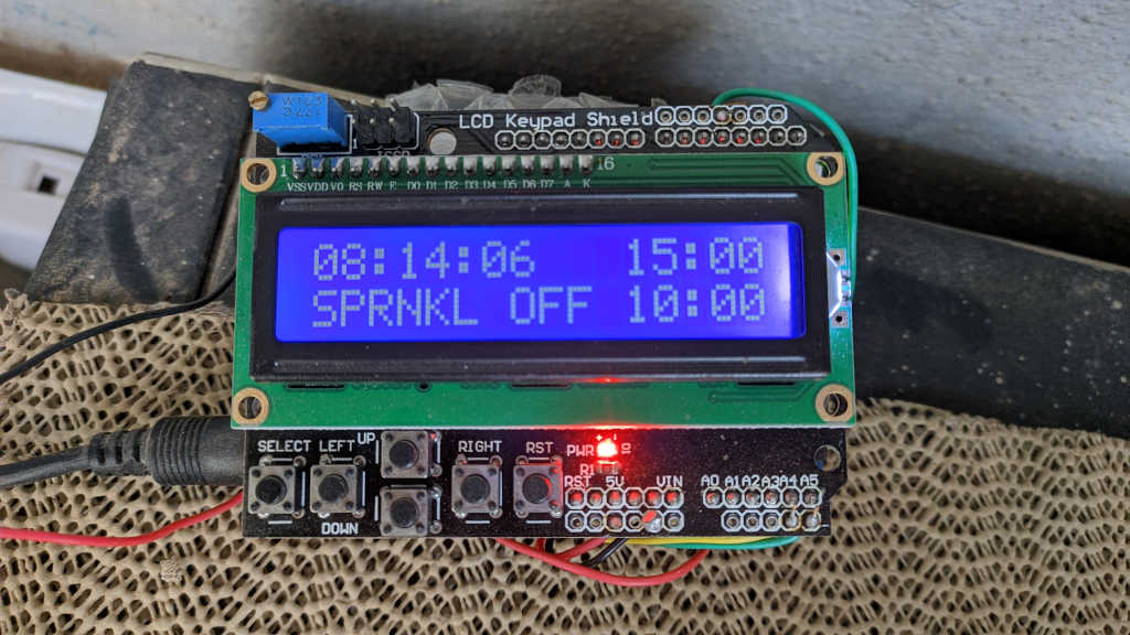
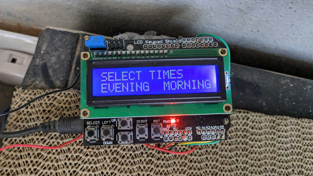
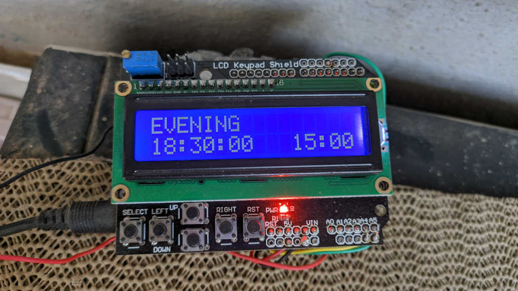
That easily fits in 56 bytes and there is still more left. Saving data is all well and good, but how do I change the time and duration? Arduino does not come with so many buttons. That is when I purchased this LCD with keypad shield for Arduino, so I can both show the status and allow the user to change information by clicking on the buttons. I rewrote the code to handle the LCD shield and the buttons. Now one can select how many times the drip needs to start in a day, the time and duration as well. This is perfect. Anyone at home can change the time and duration as they see fit. No need for me to rewrite the code :). I soldered the board but did not give it an enclosure. Because it is going to sit outside our house, there is no need to make it look fancy. Moreover the air flow keeps it cool. While the board is sitting outside, it is located in a place where it is protected from rain and direct sun light, so not a problem.
Since the board need not be reprogrammed I used a 9V adapter that powers both Aurduino and solenoid valve. Apparently the valve can work with lower than the rated 12V. Only issue is that it requires more current and takes a bit longer to open the valve. Arduino Vin can take 7-12V and the on-board linear voltage regulator will regulate it to 5V used by the board. So the 9V I supplied is not an issue.
Pressing the select button on the keypad will let you cycle through various modes and the arrow keys can be used to change the time and duration. I am not publishing my code either for v2 or v3 because it is quite long. If anyone is interested feel free to leave a comment and I can publish on github or somewhere.
The v2.0 system has been running without any issues since 9 months and v3.0 has been running for over 6 months now. One would think that is the end of the drip irrigation project, but it certainly is not. I want to add soil humidity sensor so the control system can check if there was rain that day or was cloudy and not turn on the drips depending on if the soil is sufficiently wet or not. Similarly the same sensor can be used to determine if the plants need multiple drips in a day (like morning and evening in summer). More over I want to have the control system connect to the internet so I can control and monitor it from anywhere. So those will be v4.0 and v5.0 projects for the future ;)