

Drip Irrigation Control System v1.0
If you have been reading about my organic terrace gardening project in the last few posts, you know that I have setup a drip irrigation system that automatically waters the plants everyday. Tinkering with electronics has always been my passion and this was one of those fun hobby projects that I wanted to do after retirement. Sorry, this post may be a bit too technical (electronics and code), so feel free to skip.
I have a bunch of Arduino boards lying around and I thought I should use them to setup the automatic drip irrigation system. We needed 3 control systems, one for gardens on each side of the house and another for the terrace garden. Since we have already laid out all the pipes and drips, all I needed was a way to control when the tap turns on and for how long. So the hardware I needed was a solenoid valve which needs to be attached to drip's main line and the tap, and an Arduino board that can control the valve.
I ordered this solenoid valve from amazon. After reading the rating on it, I realized that I need a power transistor to drive it because Arduino is not capable of driving it. The valve was rated at 1 Amp and 12V. I looked around for a good transistor and found that a TIP120 (darlington power transistor) would do the trick. Then I wanted to be a little adventurous and added an LCD to the mix, so I can display information from the Arduino board, like when the Arduino will switch on the valve and for how long and other status information. Here is a simplified circuit diagram I came up with.
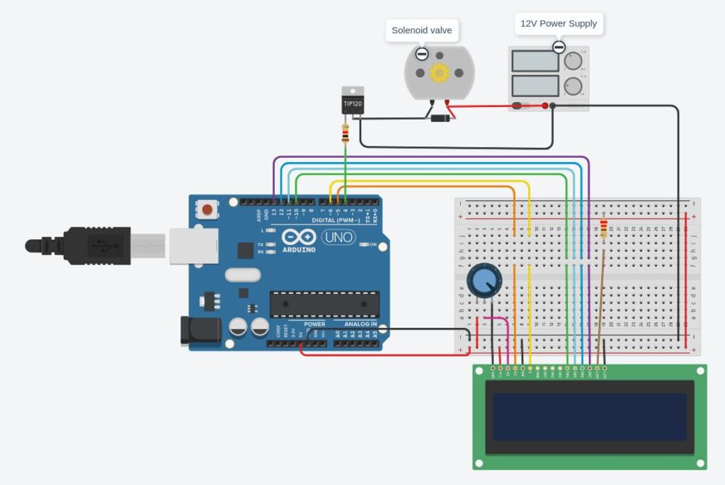
Sorry the connections look a bit messy because of the LCD display. But you get the idea. In case the font is too small, here are the connections in text format (copied from my code)
//  Arduino         LCD
// -------------------------
//  GND -----+      1 (VSS)
//  +5V      |      2 (VCC)
//  +5V --- POT --- 3 (V0)
//  5               4 (RS)
//  GND             5 (RW)
//  6               6 (E)
//  10              11
//  11              12
//  12              13
//  13              14
//  +5              15
//  GND             16
//
//
//  Arduino         TIP 120
// -------------------------
//  4  ------- 1K ----- 1 (B)
//
//        +- Valve -+
//  +12 --|         |-- 2 (C)
//        +- Diode -+
//
//  GND                 3 (E)
The diode across the valve is to protect the transistor from reverse voltage. I used a 1 K ohm resistor in front of the base of the transistor. Calculations on why I used a 1 K ohm resistor are below
Valve needs 1A, so Ic = 1A
From the datasheet
   - the saturation voltage at 1A is Vbe = 1.5V
   - Ic = 250 * Ib => Ib = 1000 / 250 = 4 mA

Arduino driving voltage is 5V
Drop in resistor = 5V - Vbe = 5V - 1.5V = 3.5V
Resistor = 3.5V / 4 mA = 3500 / 4 ~= 1 KOhm
Next, I programmed the board to turn on the valve (make Arduino pin 4 high) for 5 minutes as soon as the board was switched on. Then turn off the valve for 24 hours minus 5 minutes. Then repeat. This basically turns on the drip irrigation for 5 minutes everyday at the same time as when the board was turned on. Anytime I needed to change the duration of the drip, for example in summer I needed to make it 15 minutes, I needed to reprogram the board. I fixed this shortcoming in a later revision of the circuit, but that is for another post. Here is the Arduino code in full if anyone is interested.
 include <LiquidCrystal.h>
 include <Wire.h>

 include "RTClib.h"

 define SPRINKLER_PIN 2
 define BUTTON_PIN 7

 LiquidCrystal lcd(8,9,10,11,12,13);
 RTC_DS1307 rtc;
 bool sprinklerOn = false;
 int onDuration = 5;
 int onTimeMinutes = onDuration;
 int onTimeSeconds = 0;

 void setup() {
   Serial.begin(115200);
   lcd.begin(16, 2);
   rtc.adjust(DateTime(2019, 1, 1, 0, 0, 0));
   pinMode(SPRINKLER_PIN, OUTPUT);
   digitalWrite(SPRINKLER_PIN, LOW);
 }

 void loop() {
   showTime();
   showDuration();
   showStatus();
   delay(1000);
   updateSprinkler();
 }

 void showTime() {
   DateTime now = rtc.now();
   lcd.setCursor(0, 0);
   showZeroPaddedNumber(23 - now.hour());
   lcd.print(':');
   showZeroPaddedNumber(59 - now.minute());
   lcd.print(':');
   showZeroPaddedNumber(59 - now.second());
 }

 void showDuration() {
   lcd.print("   ");
   showZeroPaddedNumber(onTimeMinutes);
   lcd.print(":");
   showZeroPaddedNumber(onTimeSeconds);
 }

 void showStatus() {
   lcd.setCursor(0, 1);
   lcd.print(sprinklerOn ? "SPRINKLER ON   " : "SPRINKLER OFF  ");
 }

 void showZeroPaddedNumber(int number) {
   if (number < 10) {
     lcd.print('0');
   }
   lcd.print(number);
 }

 void updateSprinkler() {
   DateTime now = rtc.now();
   if (now.hour() == 0 && now.minute() == 0 && !sprinklerOn) {
     switchSprinkler(true);
   }
   if (sprinklerOn) {
     onTimeSeconds--;
     if (onTimeSeconds <= 0) {
       onTimeSeconds = 59;
       onTimeMinutes--;
       if (onTimeMinutes < 0) {
         switchSprinkler(false);
         onTimeMinutes = onDuration;
         onTimeSeconds = 0;
       }
     }
   }
 }

 void switchSprinkler(bool on) {
   sprinklerOn = on;
   digitalWrite(SPRINKLER_PIN, on ? HIGH : LOW);
 }
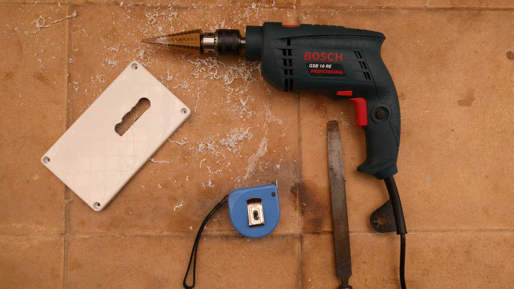
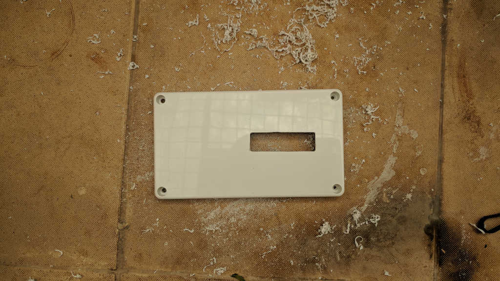
I wanted to put the circuit board in a box so I don't have to look at my ugly creation. So purchased a white plastic enclosure just big enough to fit all the electronics. Then I used a step drill bit to cut out an opening, followed by a lot of filing to make space for the LCD display to be exposed while the whole circuit will be inside the housing. It took a lot of time to get the cut out right. But hey, there are no project deadlines, so who cares :). I created an opening on the side to fix a switch and a couple of holes on the bottom of the enclosure for the wires to pass through.
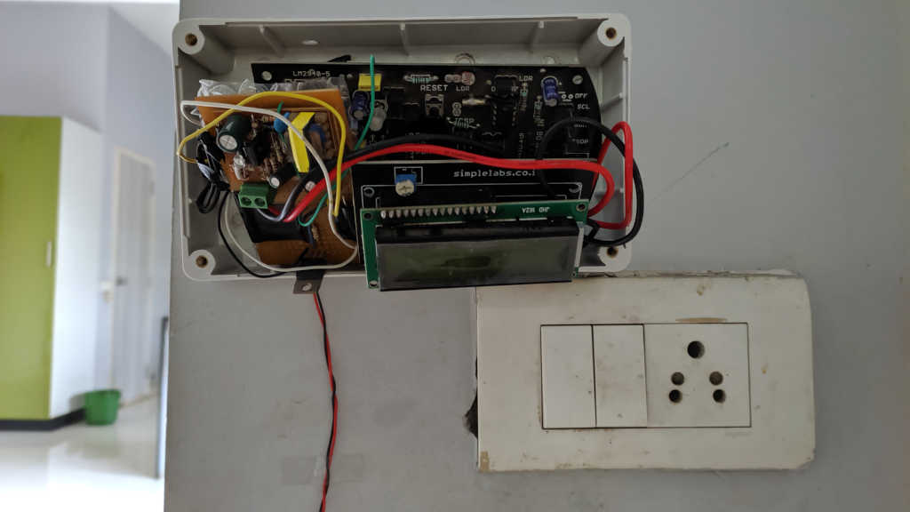
Below is the full circuit after I finished soldering everything on a PCB prototype board and crammed it into the enclosure.
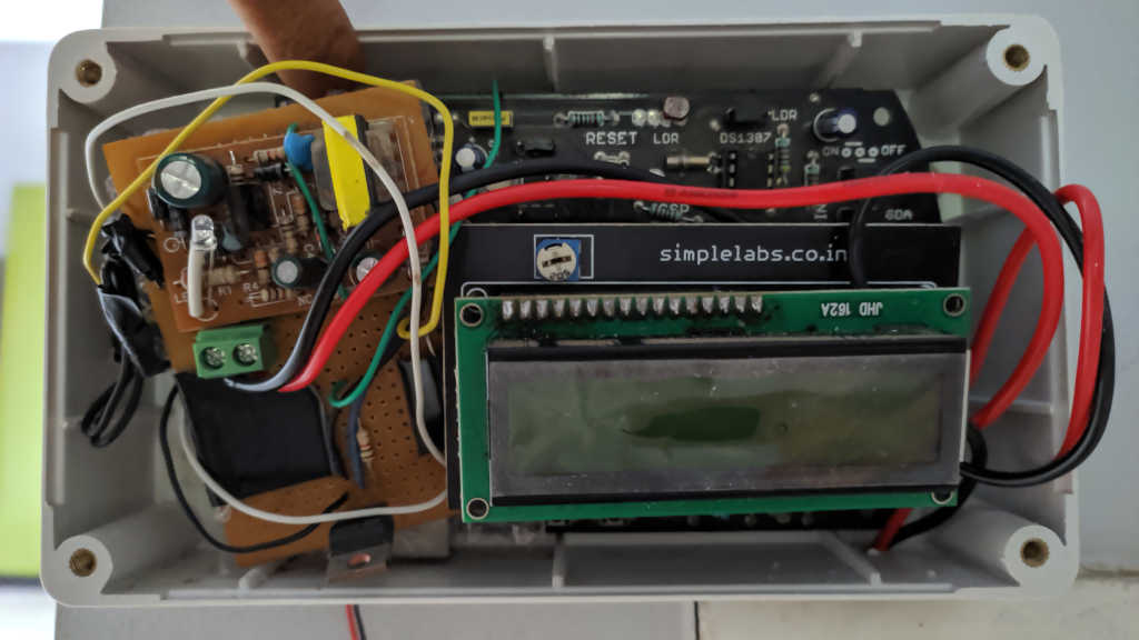
As you can see, my wire management skill is not at the level that one would like :). Notice the thick red and black wires? Those are 220V AC lines. They go to an AC to 12V DC converter board. The 12V output from the rectifier circuit goes to the Vin of Arduino. I know that 12V is near the max allowed voltage at Vin on an Arduino and the linear voltage regulator on the board might get hot, but I took the risk anyway. I live on the edge you see ;). Rest of the circuit is like I described in the circuit diagram above. I stuck the enclosure on to the wall right above a switch board so I can pull the live and neutral wires.
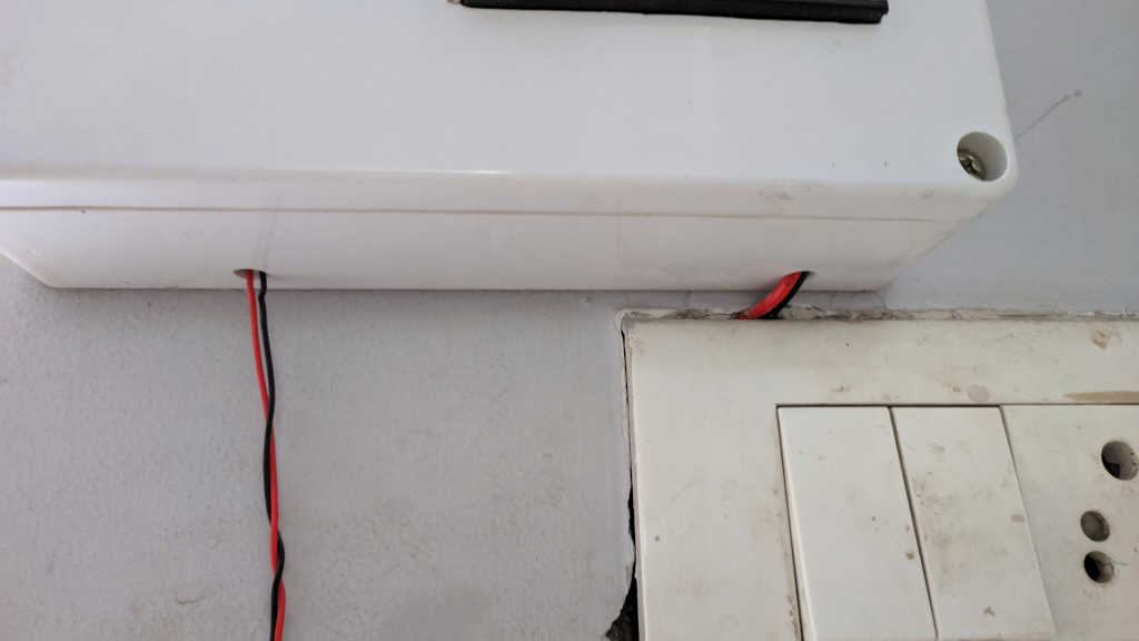
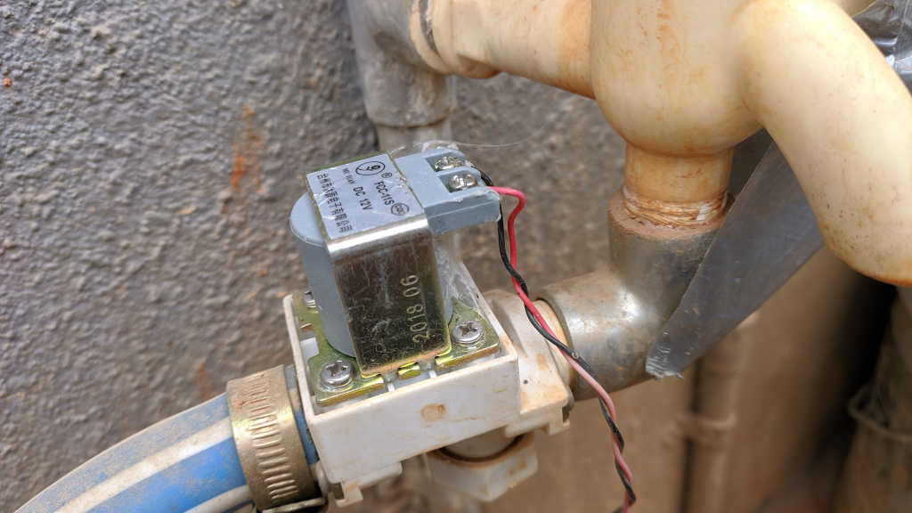
Next, I pushed in the 220 V AC wires into the enclosure using the hole I drilled under the enclosure (see picture below). Also pulled out the 12 V wires out of the enclosure to send it to the valve that is outside the house near the tap.
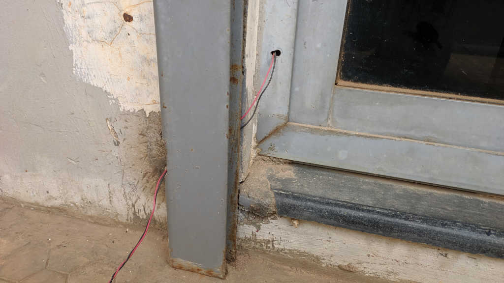
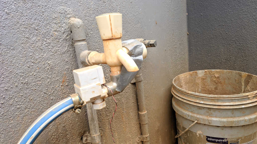
I routed the 12V wire that controls the valve from the inside of the house to the outside, drilling holes where needed. The wire connects to the valve which is connected to the tap outside. The water outlet from the tap (which is left open all the time) is connected to the valve. The valve is normally closed, so when there is no voltage across the terminals is does not allow water to pass, when a voltage is applied (signal sent by Arduino), the valve opens allowing water to flow through it and to the pipe connected to the output of the valve. The pipe is connected to drip irrigation's main line.
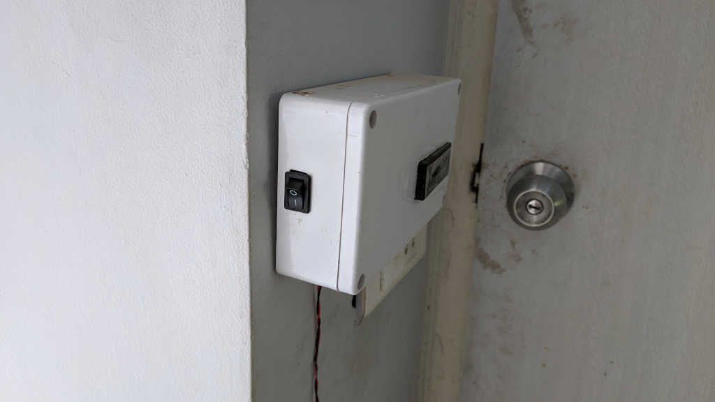
Oh and I forgot to mention, I also added a small switch to the side of the enclosure so I can turn on and off the electronics inside. Basically the 220V line goes through the switch and when the switch is off, the control turns off.
And finally, below is a glimpse of the system doing its thing :)
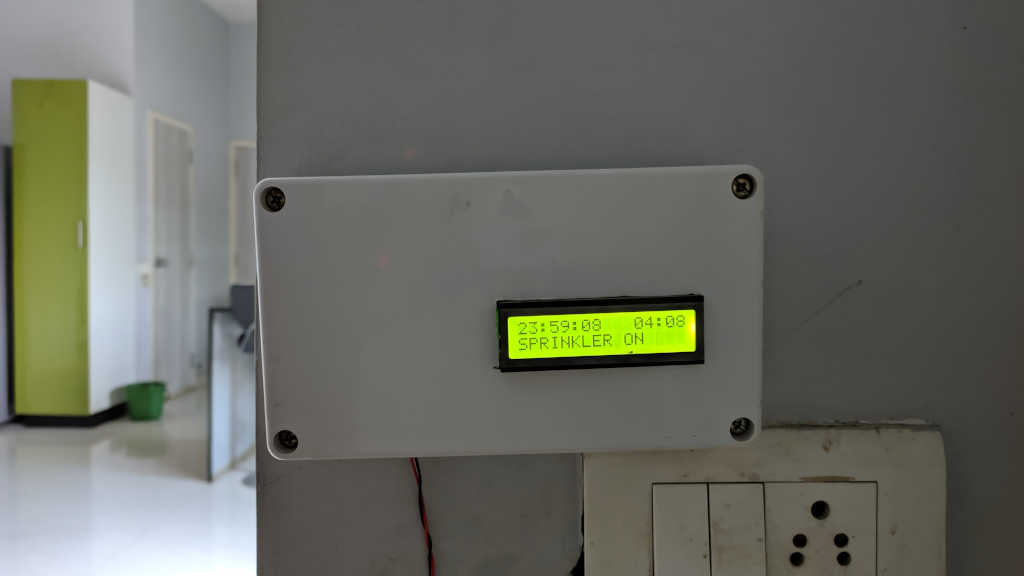
As I mentioned before, the system turns on the sprinkler as soon as it is switched on. Then it keeps the valve on for 5 minutes and updates the status on the display. As you can see, it says "sprinker on" on the 2nd line and on the top right it displays a timer for how long the sprinkler will be on. In this case another 4 minutes and 8 seconds. After that the valve will be closed. The timer on the top left of the screen tells me when the system will turn on the valve next time. The countdown timer shows 23 hours 59 minutes and 8 seconds until the next time the valve will turn on. So basically every 24 hours the valve is on for 5 minutes. Simple as that. So now I am completely hands off. The system takes care of watering the plants without my need. I do check the drips and plants once in a while to make sure they are not getting under watered or over watered.
That completes the basic setup of my system to control the drips. But I am not done yet. As usual, my projects never have an end date :). I soon realized after setting up this system that I needed to change the amount of time the drips should be on. For example in summer they need to run longer than 5 minutes. The only way to change time in this setup was to change my code and reprogram the board. Not ideal. Another problem was that in the summer my wife wanted the drips to turn on two times. Once in the morning and once in the evening. Again the board needs reprogramming. Nothing that she can do herself. So I improved the design and code. More on that in another post. By the way, this system has been running without any issues for the last one year.