

Solar Panel Project Update - Part 3
In my previous post I explained how I improved the accuracy of my DC sensors using ADS1115. But there is one problem though. The ADS1115 gives accurate reading even when the supply voltage keeps changing. Yet, the sensor values will not be correct. The reason is that if the supply voltage is changing, the reading on the sensor will also change, but the accuracy of the reading will be stable because ADS1115 is independent of power supply voltage fluctuations. For example, let’s say the supply voltage is 2.5V, then when there is no current, the DC current sensor will read 2.5V, and in the code we assume the current is 0 at 2.5V. Now if the supply voltage drops to 4V then the sensor will read 2V, which is still the mid point and indicates 0 current. But in the code we have a hard coded number that 2.5V is the midpoint and we mistakenly assume that some current proportional to -0.5V is passing through the wires. That is the problem.
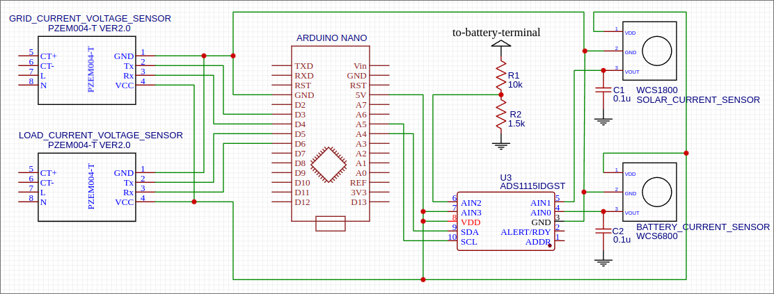
The solution is actually simple. We just need a reliable accurate way to measure the power supply voltage and then find the midpoint of it and use that for zero current condition. How can we measure the supply voltage accurately? Well we already have the ADS1115, so just connect the power supply to one of its pins. That is exactly what I did and here is the updated circuit diagram. I connected Vcc to pin AIN3 of ADS1115.
And here are the code modifications to measure Vcc and send the value via bluetooth to the android app which will do all the calculations.
#include <Adafruit_ADS1X15.h>

#define ADS1115_SDA          A4
#define ADS1115_SCL          A5

#define VCC_VOLTAGE_CHANNEL      3

class Sensors {
 private:
  Adafruit_ADS1115* ads;
  float vccVoltage = 0;

  float getVoltFromAdS(uint8_t channel) {
    return ads->computeVolts(ads->readADC_SingleEnded(channel));
  }

 public:
  Sensors() {
    ads = new Adafruit_ADS1115();
  }

  void setup() {
    ads->setDataRate(RATE_ADS1115_8SPS);
  }

  void update() {
    vccVoltage = getVoltFromAdS(VCC_VOLTAGE_CHANNEL);
  }

  void sendData(Bluetooth& bluetooth) {
    bluetooth.writeFloat(vccVoltage);
  }
};
On the android side of things, I use the power supply voltage to calculate the DC voltage and current.
  public void update(BluetoothConnection bluetoothConnection) throws IOException {
    rawData.powerSupplyVoltage = bluetoothConnection.readDouble();
    double midPoint = rawData.powerSupplyVoltage / 2;

    double value = bluetoothConnection.readDouble();
    rawData.solarCurrent = ConfigData.getRealValue(
        ConfigData.Type.SOLAR_CURRENT, value, midPoint);

    value = bluetoothConnection.readDouble();
    rawData.batteryCurrent = ConfigData.getRealValue(
        ConfigData.Type.BATTERY_CURRENT, value, midPoint);

    value = bluetoothConnection.readDouble();
    rawData.batteryVoltage = ConfigData.getRealValue(
        ConfigData.Type.BATTERY_VOLTAGE, value, midPoint);
  }
More code below and remember to read the comments carefully because that is where all the details are if you care about taking accurate measurements from your DC sensors. I did not want to elaborate the same again in the post, so comments are the way to go :).
public class ConfigData {
  public enum Type {
    BATTERY_VOLTAGE,
    SOLAR_CURRENT,
    BATTERY_CURRENT,
  }

  // The formula from datasheet http://www.winson.com.tw/uploads/images/WCS1800.pdf
  // for wcs1800 is raw reading from arduino (reading) = 0.0631 * current + 2.5197
  // so current = (reading - 2.5197) / 0.0631
  // offset = 2.5197 - midPointOf(5V) = 2.5197 - 2.5 = 0.0197
  private static final double SOLAR_CURRENT_OFFSET = 0.0197;
  // WCS1800 sensitivity is 0.0631 V/A, so 1 / 0.0631 will give the factor to multiply
  // with the voltage readings. However, the sensitivity of 0.0631 is when the voltage
  // is 5.0V. Since the actual power supply voltage could be different (determined by
  // the mid-point reading), we have to scale the sensitivity by
  // 2.5 / supply_voltage_midpoint.
  // The real number from empirical data seems to suggest a different number though
  private static final double SOLAR_CURRENT_SENSITIVITY = 1 / 0.066 * 2.5;

  // The formula from datasheet http://www.winson.com.tw/uploads/images/WCS6800.pdf
  // for wcs6800 is raw reading from arduino (reading) = 0.0607 * current + 2.4718
  // so current = (reading - 2.4718) / 0.0607
  // offset = 2.4718 - midPointOf(5V) = 2.4718 - 2.5 = -0.0282
  // The real number from empirical data seems to suggest a different number though
  private static final double BATTERY_CURRENT_OFFSET = 0.037215;
  // WCS6800 sensitivity is 0.0607 V/A, so 1 / 0.0607 will give the factor to multiply
  // with the voltage readings. However, the sensitivity of 0.0607 is when the voltage
  // is 5.0V. Since the actual power supply voltage could be different (determined by
  // the mid-point reading), we have to scale the sensitivity by
  // 2.5 / supply_voltage_midpoint.
  private static final double BATTERY_CURRENT_SENSITIVITY = 1 / 0.0607 * 2.5;

  // Empirically found value
  private static final double BATTERY_VOLTAGE_SENSITIVITY = 9.22;

  public static double getRealValue(Type type, double value, double midPoint) {
    switch (type) {
      case BATTERY_VOLTAGE:
        return value * BATTERY_VOLTAGE_SENSITIVITY;
      case SOLAR_CURRENT:
        return -getCurrent(value, midPoint, SOLAR_CURRENT_OFFSET,
            SOLAR_CURRENT_SENSITIVITY);
      case BATTERY_CURRENT:
        return -getCurrent(value, midPoint, BATTERY_CURRENT_OFFSET,
            BATTERY_CURRENT_SENSITIVITY);
      default:
        throw new RuntimeException("Code not implemented for " + type);
    }
  }

  private static double getCurrent(
      double reading,
      double midPoint,
      double offset,
      double sensitivity) {
    return (reading - midPoint - offset) * sensitivity / midPoint;
  }
}
As you will notice from the datasheets, the curve to calculate the current from voltage reading of the sensor is not a simple y = mx + c sort of equation. The curves are non-linear but the datasheet provides an approximation where y = current, m = sensitivity, x = voltage reading and c = offset. If you lost me by this point, don’t worry. If you build your own circuit you will easily understand what I am talking about. Anyway, the m and c are supposed to be specific numbers, but they were different when I used the sensors (which happens).

I measured c by removing the current sensor from the wire, which means it should measure zero current which should be equal to mid-point of Vcc, but there will be a slight offset which is what c is. To measure m, I had to load the wire with different currents and measured the slope. The reason I am explaining all this is so you understand how much work it takes to complete the project. Which is why I could not work on any other project as this is taking up all my time.
Anyway, at the end of all this, the measurements were much better than what I got earlier and would not drift based on source voltage fluctuations. Earlier my readings would be different depending on whether my house is running on batteries or grid. You see, when running on grid, the supply voltage would be around 4.9V or something and when the house is running on batteries the supply voltage would be around 4.8V or something because of drop in AC voltage plus any deviation in the load by the arduino board (because it operates a relay) which causes sag in the supply voltage. Now, I don’t have any problems with supply voltage, but I still have problems with temperature drift. I will explain how I tackled that problem in my next post.