

Solar Panel Project Update - Part 2
This is a continuation of my previous post giving updates about my solar panel setup. As you will probably remember from that post, I found a good sensor that would measure AC voltage and current accurately and I was satisfied and very confident about the data coming from the sensors. However, I cannot say the same about my DC measurements. Many components in the system should be measured in DC including solar panel current, battery voltage and current etc. My initial set of sensors were not accurate and used to drift quite a bit with supply voltage and ambient temperature. So I set out to find better sensors and upgraded them and I cover part of that story in this post.
If you recall, I was using WCS1800 to measure solar panel current, a WCS6800 to measure battery current and a voltage divider to measure the battery voltage. Note that the solar panel voltage is the same as the battery voltage since I am using a PWM charger. I connected the output from all these sensors directly to my arduino nano inputs. Of course I used 0.1uF ceramic capacitors at the outputs of the current sensors as suggested by the datasheet. Yet the readings would be quite off from what my clamp meter and multimeter would read. Not only that but the reading are very jittery and there is a lot of variation from one reading to the next. The below circuit diagram illustrates my design.
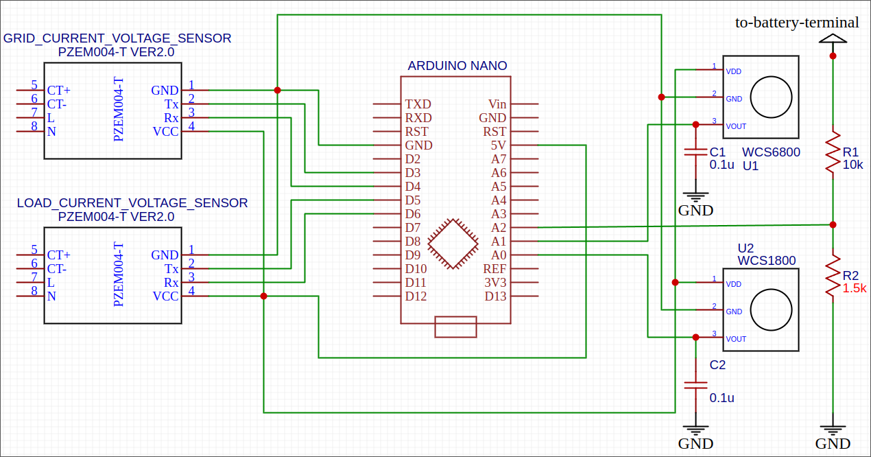
The readings would differ when the supply voltage changes. It also varied during day and night time when the ambient temperature would change. Not just that but as seasons changed, the sensors would keep drifting. This made my code quite complicated because I had to constantly change offset constants to compensate for the drifts.
At this point I was contemplating if I should maintain a temperature compensation lookup table. Then if I add an accurate temperature sensor I could look up the right offsets. But this just means I need to find not only an accurate temperature sensor, but also a reliable way to read the measurements accurately. Remember that I can only read accurate values if my reference voltage is accurate and as I already mentioned, my reference voltage (power supply) is very unreliable. I felt there should be a better solution.
Enter ADS1115, a 16 bit ADC with internal reference voltage. Since it has an accurate internal voltage reference, I don’t have to worry about supplying a good quality reference to arduino for accurate measurements. Moreover, it is very stable over various operating temperature with an offset drift of only 0.005 LSB/ºC. Which means for a 20 degrees change in temperature, it would drift only by 0.1 volts for my readings. Remember however that this does not mean that if there is a drift in the sensors itself, then it cannot fix that. What this device does is that it reads the value more accurately than arduino itself.
If I was not clear, let me explain with an example. Say the WCS1800 is reading 2.5V with a supply voltage of 5V. That means the current reading is 0 amps because 2.5V is the midpoint of 5V. Any reading less than 2.5V means current going in one direction and anything about 2.5V is current going in the other direction. Now, if I use an arduino nano, I might read a voltage of 2.4V or 2.6V depending on the power supply voltage and temperature. With ADS1115, the reading will be more like 2.49V to 2.51V depending on various factors. So the measurement has become more accurate.
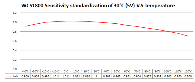
However, lets say because of temperature drift, the WCS1800 sensor itself is reading 2.4V although it should ready 2.5V at zero current, then ADS1115 cannot help because it will still be accurate and read something like 2.4V although it should be 2.5V. So how accurate is a WCS1800 with changes in temperature? Looking at the graph below, it is not too bad at operating voltage (10ºC to 40ºC) if you ask me.
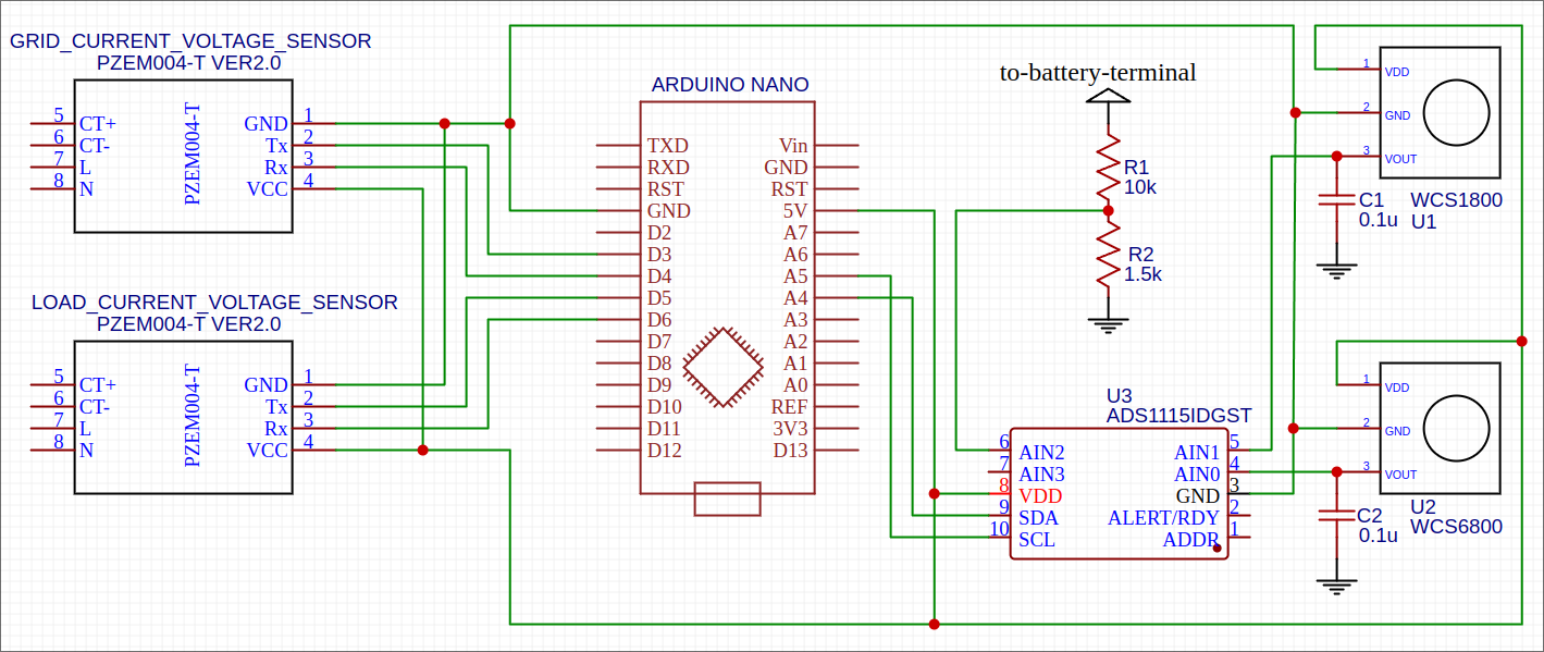
So I decided not to use a temperature sensor just yet and changed my circuit design to use ADS1115 and this is the new circuit diagram.
As usual, on the software side of things, we already have a library to interface with ADS1115. All I needed to do was add adafruit/Adafruit ADS1X15@^2.4.0 to my platformio.ini file.
[env]
platform = atmelavr
framework = arduino
monitor_speed = 115200
lib_deps =
	paulstoffregen/Time@^1.6
	mandulaj/PZEM-004T-v30@^1.0.0
	adafruit/Adafruit ADS1X15@^2.4.0
	SPI
Next, I initialize ADS1115 and read the data as follows:
#include <Adafruit_ADS1X15.h>

#define ADS1115_SDA          A4
#define ADS1115_SCL          A5

#define BATTERY_CURRENT_CHANNEL  0
#define SOLAR_CURRENT_CHANNEL    1
#define BATTERY_VOLTAGE_CHANNEL  2

class Sensors {
 private:
  Adafruit_ADS1115* ads;
  float batteryVoltage = 0;
  float batteryCurrent = 0;
  float solarCurrent = 0;

  float getVoltFromAdS(uint8_t channel) {
    return ads->computeVolts(ads->readADC_SingleEnded(channel));
  }

 public:
  Sensors() {
    ads = new Adafruit_ADS1115();
  }

  void setup() {
    ads->setDataRate(RATE_ADS1115_8SPS);
  }

  void update() {
    batteryVoltage = getVoltFromAdS(BATTERY_VOLTAGE_CHANNEL);
    batteryCurrent = getVoltFromAdS(BATTERY_CURRENT_CHANNEL);
    solarCurrent = getVoltFromAdS(SOLAR_CURRENT_CHANNEL);
  }

  void sendData(Bluetooth& bluetooth) {
    bluetooth.writeFloat(batteryVoltage);
    bluetooth.writeFloat(solarCurrent);
    bluetooth.writeFloat(batteryCurrent);
  }
};
That is all for this part. Even with this new design, there is a problem with the sensor data. See if you can figure it out. I will explain how I fix it in my next post since this one is already pretty long.