

Collecting Data From Solar Panel Setup
After having setup the solar panel on our terrace, I wanted some data. Specifically I wanted to know the panel output over the course of the day and how much energy savings we are enjoying. The solar management unit (SMU) gives some details about the instantaneous power output and energy savings. But for some reason I felt the numbers look a bit too optimistic. Moreover I could not get more granular data from it. I guess it has more to do with not invented here syndrome. Either way I decided to hook up some sensors myself to gather all the data I'd like from it.
I should probably preface by saying that I might get a bit technical with respect to electronics and software engineering. So feel free to skip the post if you are not so inclined.
If you are interested, here are all the previous posts on solar panel project in chronological order
- Solar Panel Project – Inception
- Solar Panel Project – Do It Yourself
- DIY Solar Panel Project – The Ingredients
- Wiring Solar Panels, Solar Management Unit and UPS
- Optimal Tilt For Solar Panels
- Solar Panel Performance And Energy Savings
Sensors
I wanted to add 4 voltage and current sensors. One for each of the following
- Solar panel output
- Battery terminals
- Grid output
- Load input
Knowing voltage (V) and current (I) should let me calculate instantaneous power (V x I) at each of those points.
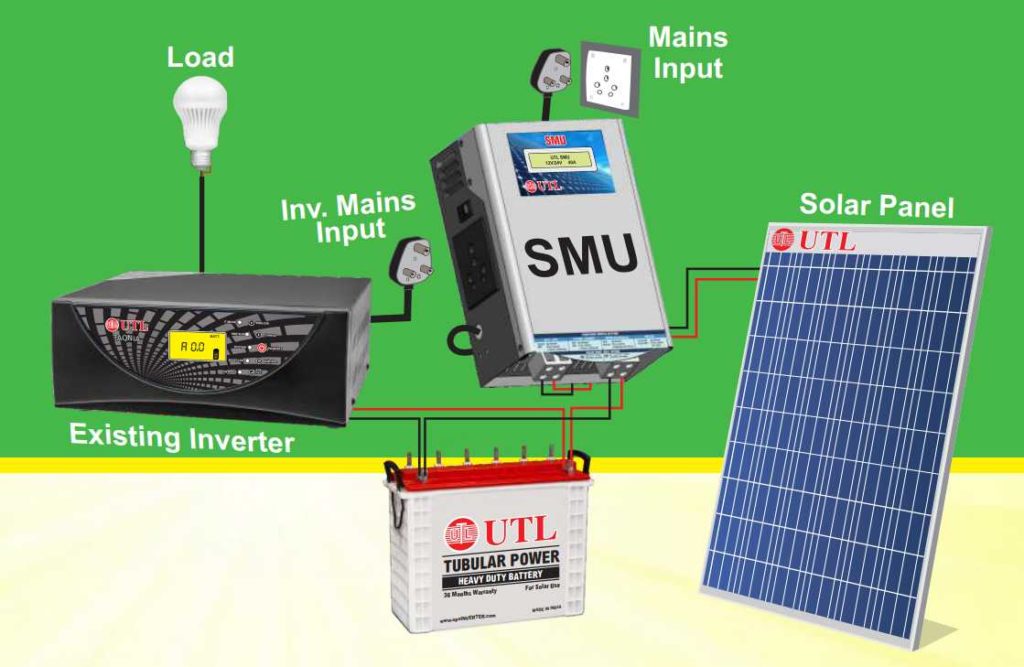
Lets go back to the solar panel connection diagram one time (see diagram below). The solar panel is connected to SMU which sends the power to charge the batteries. The inverter/UPS is connected to the grid, batteries and load (power to the house).
Hooking things up
I got a couple of ZMPT101B voltage sensors to measure AC voltages at the grid and load. Then I got a couple of ACS712 AC current sensors (20 A) for measuring grid and load currents. Got one WCS1800 DC current sensor (35 A) to measure solar current. I made a voltage divider circuit to measure battery voltage. Did not go with a voltage sensor for the solar panel since it will be the same as the voltage across the battery when they are connected for charging. I also did not go with a current sensor for the battery because I can derive it as follows
battery current = (load current - solar current - fixed UPS running current) / UPS efficiency
I know that's a lot of jargon, but if someone is interested they can follow my design. Next, I pried open the wall socket connections to hook up all the AC voltage and current sensors. A fair warning if you are attempting to do this. You are playing with 220 V mains supply which is dangerous!
Next I unscrewed the battery terminals and connected wires to my DC voltage sensor. Warning again, you might see sparks flying when you connect the battery cables. Slid in the WCS1800 current sensor into the solar panel wiring.
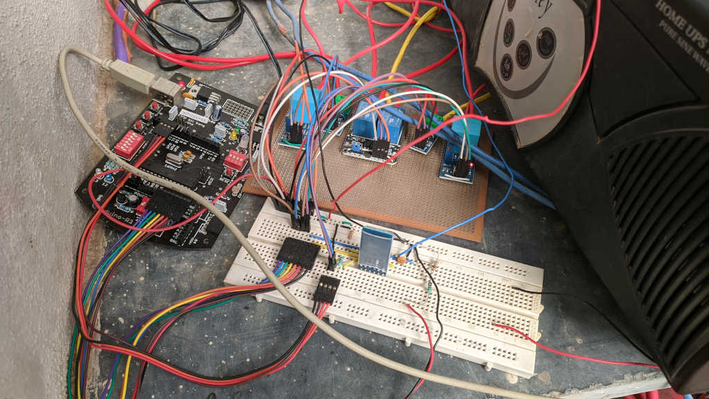
Finally I hooked up all the sensors to analog inputs of an Arduino board. The Arduino board is also connected to a HC-05 Bluetooth adapter. Then I programmed the board to send all the sensor data via Bluetooth to any device that connects to it. What you see below is the mess of wires after all the sensors are connected.
Software
What good is the data if you cannot visualize it? So what I wanted to do was to build nice interface for me to see how the power is moving along. To that end I programmed an old android tablet to connect to the Arduino board via Bluetooth and capture the sensor data. Remember from one of my earlier posts where I mentioned I wanted to use Flutter for a couple more projects? Well, this is one of them. Below is a snapshot of the app that I built.
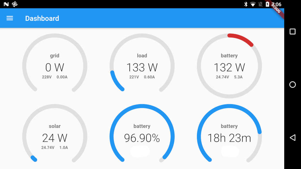
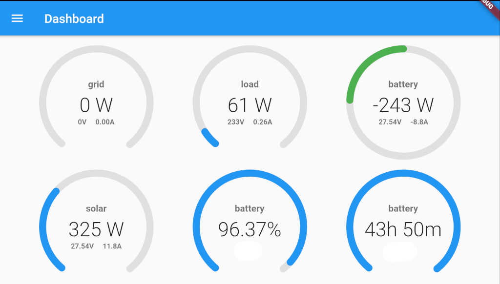
Now I know exactly how much load is on the battery. How long my battery will last with the current load. How much solar power is being generated and much more. Below you will find another screenshot of the app. You can make the following observations from it
- Grid is disconnected by SMU
- Load is 61 W (only my media center is running along with some laptop and phone chargers)
- Solar panel is generating 325 W which is more than the rated 320 W for the panel. You know why that is the case don't you?
- Excess power is fed into the battery at 243 W. Since there will be some losses the full 325 - 61 = 264 W is not being pumped. Losses account for 21 W in my case.
- From my calculations, about 96.37% of the battery capacity is still left.
- Based on a load of 61 W and available battery capacity of 96.37%, the battery should last for about 43 hours and 50 minutes!
- Of course as the load changes, so does the remaining time on battery
So as you can see, I have a lot of useful data here. I can check the battery capacity any time of the day and decide if I need to shed some load to extend the battery life.
Something's not right here
After building the whole thing, I found out that I am actually wasting away some solar power. While the SMU was doing a good job of disconnecting the grid when the solar power can generate enough power, it is not doing the best job. I found out two issues with the way the SMU was working. So I decided to take control of the situation and build my own logic on when to disconnect from the grid so as to maximize the usage of generated solar power. More on that in my next post.
For now suffice it to say that it took me 3 months from the time I ordered the solar panel, to setting it up, to building the whole software and electronics. People wonder what I do with all the free time after retirement. This is what I do :). For almost anyone it is waste of time, but for me hobby projects are one of the best ways to spend my time!