Solar Panel Project Update - Part 1
It has been a while since I gave any updates on my solar panel project so I thought I should write a post on it. This can get pretty technical so if you are not into electronics or software, you can skip. Since I last reported about my design I’ve made a few changes mainly to increase the stability of the system. What happened was that in the long run, I found some problems that rear their head sometimes intermittently. As a result I had to change the design to recover some components from their weird state. In addition I reduced the variability of readings by the sensors.
For the past one year I have been quite busy making changes to both hardware and software of the solar panel. Although I have not been giving any updates, those changes were taking up all my hobby project time and I did not start any other new project. I will try and recollect the issues and how I fixed them in the same order as they happened. Since there were lots of issues and fixes I might end up writing multiple posts interspersed between other financial posts so you don’t get bored reading just technical information. I will try to keep these posts short as well.
The first issue I was having with my sensors were that the readings varied quite a bit not just throughout the day but as the seasons changed as well. All my current and voltage sensors were reading values that change quite a bit depending on various factors including supply voltage to the arduino, temperature, humidity and other conditions. If you recall, I was initially using ZMPT101B for measuring AC voltage and ACS712 for measuring AC current, both of which were showing a lot of variability.
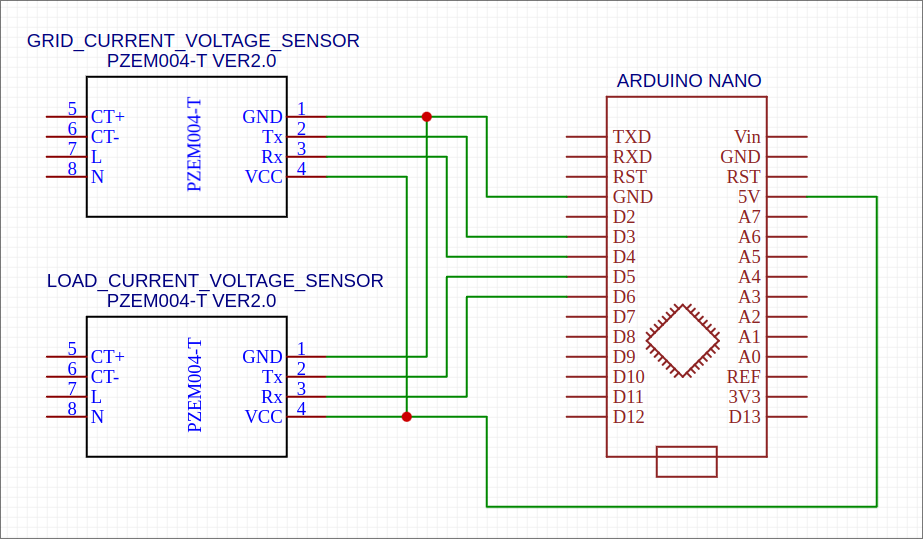
I researched a bit and found that PZEM004T can measure both voltage and current all in one package. In addition, it can measure power factor, frequency, power and energy. But the most important thing for me was that it was very accurate and the variability was quite low. I bought a couple of those sensors, one for measuring the load side and another for measuring the grid side. Then I changed the hardware design and the software that goes with it in arduino. You can checkout the new design below.
On the software side, conveniently there is already a library to read data from PZEM004T. If you recall, I use platformIO to write and build my arduino code. So all I had to do was to add mandulaj/PZEM-004T-v30@^1.0.0 to lib_dep in the platformio.ini file.
[env]
platform = atmelavr
framework = arduino
monitor_speed = 115200
lib_deps =
	paulstoffregen/Time@^1.6
	mandulaj/PZEM-004T-v30@^1.0.0
	SPI
Next, I initialize the sensors and read the data. Here is the simplified actual code.
#include <PZEM004Tv30.h>

#define GRID_RX_PIN          3
#define GRID_TX_PIN          4
#define LOAD_RX_PIN          5
#define LOAD_TX_PIN          6

class Sensors {
 private:
  PZEM004Tv30* gridSensor;
  PZEM004Tv30* loadSensor;

 public:
  Sensors() {
    gridSensor = new PZEM004Tv30(GRID_RX_PIN, GRID_TX_PIN);
    loadSensor = new PZEM004Tv30(LOAD_RX_PIN, LOAD_TX_PIN);
  }

  void sendData(Bluetooth& bluetooth) {
    bluetooth.writeFloat(gridSensor->voltage());
    bluetooth.writeFloat(gridSensor->current());
    bluetooth.writeFloat(loadSensor->voltage());
    bluetooth.writeFloat(loadSensor->current());
  }
};
That’s it. After using the new sensors, my load and grid data is so much cleaner. I will explain how I cleaned up sensor data coming from DC voltage and current sensors in my next update on solar panel project.


