

DC Energy Measurement Using PZEM 017
You might remember that I have been looking for an accurate DC current measuring device for a long time for my solar project. The hall effect sensors I have been using in my solar project was inaccurate. Basically the zero current point drifts quite a bit depending on the ambient temperature and power supply voltage. While a shunt would give more accurate zero cross overs, I did not want to modify my setup to use it. You see, the problem with shunt resistor based sensors was that they have to be inline with current. Which means I have to remove a bunch of wiring from my battery and UPS and insert these sensors inline. I was not willing to do that. However I recently came across another project which would be a good fit to test out these shunt resistor based sensors. So I tried a couple of them and what follows is my experience with one of them.
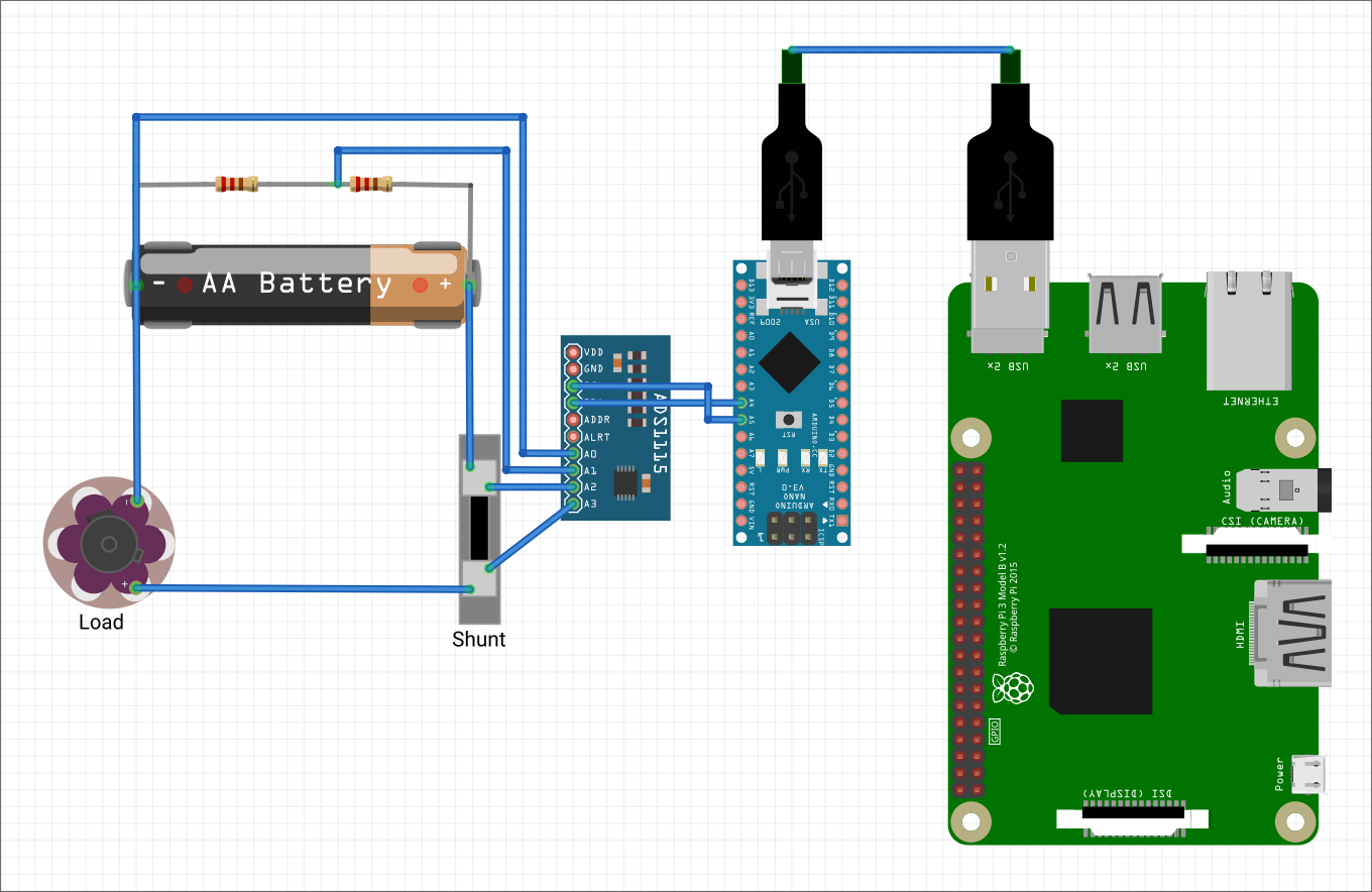
I recently started working on a new hobby project about which I will write in another post. But suffice to say that I needed a way to measure DC current accurately so I can plan how big of a battery capacity I would need. I actually needed to measure the energy used by a bunch of electronics. Since I already have good sensors to measure voltage (ADS 1115), I thought if I have a good current sensor, my work would be done. Initially I decided to go with a shunt resistor and use ADS 1115 to measure the voltage difference and thus the current. The values of ADS 1115 would be measured by an Arduino or ESP 8266 processor and then the data will be sent to a Raspberry Pi to upload the data to the cloud. That was my plan and came up with the following circuit diagram (imagine the AA battery in the circuit diagrams to be a 12V battery).
I already have a raspberry pi, so all I need to do is buy a shunt resistor, an ADS 1115 and an Arduino nano. As I was browsing for some shunt resistors, I chanced upon PZEM 017. It is an interesting device. It not only measures voltage, current and power, but also energy! That is just the perfect device I was looking for. I can skip the ADS 1115. I wouldn’t even need a dedicated processor (Arduino nano) to continuously measure voltage and current to calculate power and then use the time difference between readings to measure energy. The best part is that the PZEM 017 can even interface directly with a laptop or in my case with a Raspberry Pi to transfer the sensor information to the cloud.
The only problem is that it is quite expensive at Rs. 1,665 (at the time I purchased) it. However, I wouldn’t need to buy the shunt resistor (Rs. 270), ADS 1115 (Rs. 300) and the Arduino Nano (Rs. 230) which adds up to Rs. 800. Still, this device is twice as expensive as building something from scratch. I weighed the pros and cons and decided to buy the device anyway because I felt that the savings in time might be worth it. Remember that if I buy all the parts myself, I will have to do all the wiring, soldering as well as programming the Arduino Nano. Human beings are not rational, but rationalizing animals :). Anyway, with PZEM 017, my design will be simplified as shown below.
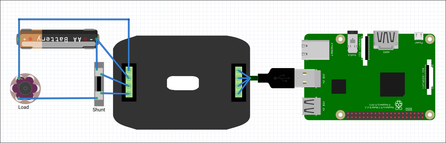
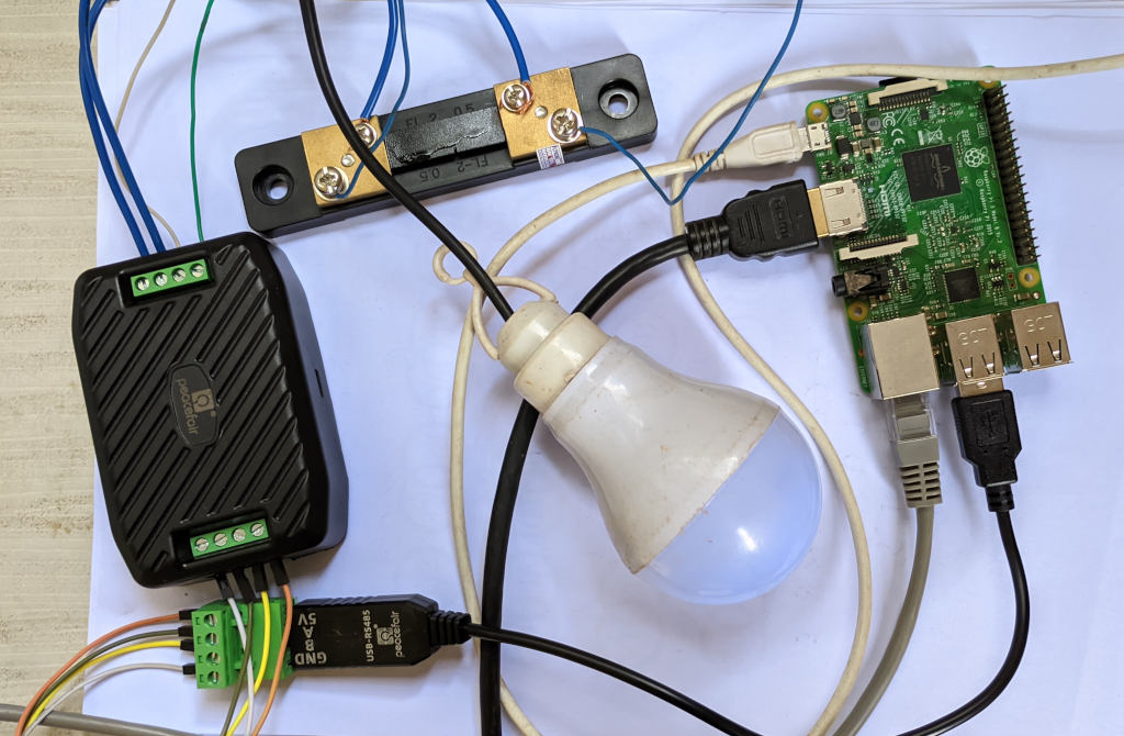
You will notice that I don’t even need the voltage divider circuit because PZEM 017 is capable of reading voltage readings anywhere from 0.05 VDC to 300 VDC. Likewise, it can read current up to 300 A depending on the shunt used. A lot of things will be simplified. One problem I had with the part in robu.in is that it comes with a 300 A shunt. So I had to purchase a 50 A shunt in addition to PZEM 017 because I don’t need such a wide current range (which reduces precision) for my project. The parts arrived in a couple of days and I was pretty happy with the quick shipping. I completed the wiring and connected my Raspberry Pi to it. The bulb that you see in the picture is the load. It is a 12V DC bulb and not the 220V AC kind.
On Raspberry Pi running Raspbian OS, I had to install the following
sudo apt install python3-pip
pip install minimalmodbus pyserial
I used the code from https://github.com/croutonso/PZEM017modbus and made minor modifications because it was not working as-is with my device.
import minimalmodbus
import serial
import time
from contextlib import closing

DEVICE_ADDRESS = 0x01
BAUD_RATE = 9600
TIMEOUT = 1
PORT = '/dev/ttyUSB0'

def connect_modbus_device():
    instrument = minimalmodbus.Instrument(PORT, DEVICE_ADDRESS)
    instrument.serial.baudrate = BAUD_RATE
    instrument.serial.bytesize = 8
    instrument.serial.parity = serial.PARITY_NONE
    instrument.serial.stopbits = 2
    instrument.serial.timeout = 1
    return instrument

def read_pzem_data():
    instrument = connect_modbus_device()
    try:
        values = instrument.read_registers(0x0000, number_of_registers=6, functioncode=4)
        voltage = values[0] / 100
        current = values[1] / 100
        power_low = values[2]
        power_high = values[3]
        power = (power_high << 16) + power_low
        energy_low = values[4]
        energy_high = values[5]
        energy = (energy_high << 16) + energy_low
        print(f"Voltage: {voltage} V")
        print(f"Current: {current} A")
        print(f"Power: {power * 0.1} W")
        print(f"Energy: {energy} Wh\n")
    except minimalmodbus.IllegalRequestError as e:
        print(f"Error: {e}")
    finally:
        instrument.serial.close()

if __name__ == "__main__":
    while(1):
        read_pzem_data()
        time.sleep(1)
The readings seem reasonably accurate when compared with my multimeter. There are a couple of problems though. One, the device is not able to measure current below 0.02 A. Which is fine I guess. Another problem is that it can measure current going only in one direction. While my new project does not need bidirectional current measurement, if I had to use this for my old solar panel project it would not work. The UPS can charge the battery and pull current from the battery which means it is bidirectional and this device will not be of help. My hall effect based sensor does not have this issue. So if you are looking for an energy meter without the above constraints, you can try this one out. If you buy a MAX485 TTL To RS485 converter then you can interface with an Arduino board (via serial interface) instead of using Raspberry Pi (via USB).