

DC Energy Measurement Using INA226
In an earlier post I wrote about measuring DC energy using PZEM 017. If you recall, I ended the article with a couple of remarks. One was that the device was unable to measure current below 0.02 A. But the bigger problem was that the device could only measure current in one direction. It is uni-directional current sensor. I cannot use this device with my UPS to measure charging and discharging current since I need a bidirectional current sensor in that case. After some searching around I found a few options and one good sensor which is the INA226. So here is a write up of my experience with it. This can get a bit technical, so if you are not into electronics, give this a skip.
After my experiment with PZEM 017, I decided to find a bi-directional current sensor. I found a few of them, but each had their pros and cons. One of the most common and easiest to find device was INA219. It can measure current, bus voltage and power. I can calculate energy from that information if I need to. It would have been the perfect device except that it can only read a maximum bus voltage of 26V. Since I have two 12V batteries in series, the voltage exceeds it. The charging voltage can vary anywhere from 27.4 V to 30 V depending on which charging stage the battery is in. Under bulk charging, the voltage can reach up to 27.4 V which already exceeds the limit. When the battery is in absorption stage it can go as high as 28 V and in equalization it can even reach 30 V.
Another option would be INA169 which is tolerant of 60 V. It can work. In fact in the future I want to upgrade my battery setup to 48 V and this sensor would even work at that time. Unfortunately though, this sensor can only measure current and not voltage. So I need another sensor, basically ACS1115 like I already have to measure battery voltage. Which is fine I guess. But another problem with INA169 is that the output is analog, unlike the digital output of INA219 (I2C). Which means, the microprocessor (Arduino in my case) has to be close to the sensor and also needs an accurate ADS. Again ACS1115 to the rescue. However, the biggest problem with this device is that it is not a bi-directional current sensor. Back to square one.
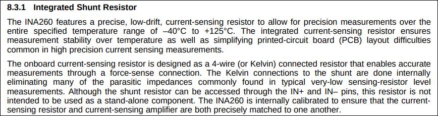
The search continued and I landed on INA260 which seemed to fit the bill. The maximum voltage it can handle is 36 V, well beyond what I need as of now. It is bi-directional, can be installed low side or high side. Can measure current, voltage and power. Has digital output (I2C), so no need for an ADC. The only problem – it cannot be used with an external shunt. The datasheet mentions as much (see picture below). The internal shunt only allows a maximum of 15A. My UPS charges with 10 A and discharge current can be as high as 30 A.
I finally arrived at INA226. It has all the characteristics of INA260 but with a facility to attach external shunt. Although it is not accurate as INA260, it works for me. It is better than INA219 in that it has a 16-bit ADC vs the 12-bit in INA219. Only wish I have is if it can handle 60 V that would make it future proof too. Anyway, I ordered one and proceeded to built a circuit diagram to test it out (see picture below).
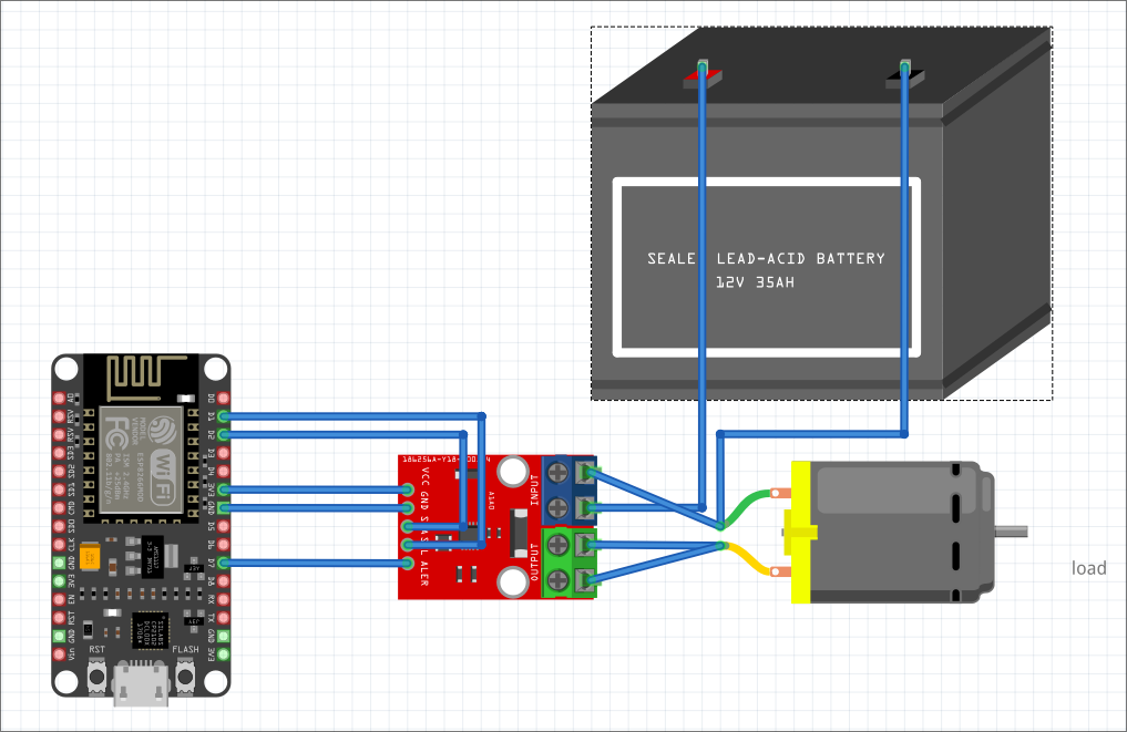
I decided to see if I can build something quickly with a few parts. I connected an ESP 8266 to INA226 which is connected to the shunt. For load, I used an LED which takes power from the ESP 8266 itself (see picture below). So the current draw will be small. Lets see if the INA226 will be able to detect it.
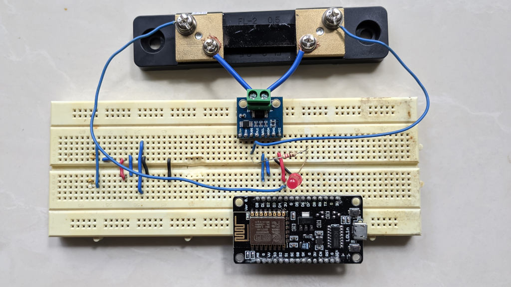
Now there is one interesting twist with the INA226 module I purchased which is that it comes with a 0.1 ohm shunt already connected on the PCB. Thankfully the module also has terminals to connect external shunt as well. I could carefully remove the R100 SMD from the PCB and connect an external shunt, but I decided to just add the shunt in parallel to R100. The equivalent resistance then becomes
R = R1 x R2 / (R1 + R2)
In my case, R1 = 0.1 ohm and R2 (external shunt) = 0.0015 ohms. So R = 0.001477833 ohms. Next I programmed the ESP 8266. Thankfully, there is a library already available for Arduino. Here is the code (with error checking and logging removed to keep it short):
#include <Arduino.h>
#include <Wire.h>
#include <INA226_WE.h>

#define I2C_ADDRESS 0x40

INA226_WE ina226 = INA226_WE(I2C_ADDRESS);

void setup() {
  Serial.begin(115200);
  Wire.begin();
  if (!ina226.init()) {
    Serial.println("Failed to init INA226. Check your wiring.");
    while (1) {}
  }

  ina226.setAverage(AVERAGE_16);
  ina226.setConversionTime(CONV_TIME_8244);
  ina226.setMeasureMode(CONTINUOUS);
  ina226.setCurrentRange(MA_800);
  // Using a 75mv / 50A shunt in parallel with 0.1 ohm
  ina226.setResistorRange(0.001477833, 50.0);
  ina226.waitUntilConversionCompleted();
}

void loop() {
  float shuntVoltage_mV = ina226.getShuntVoltage_mV();
  float busVoltage_V = ina226.getBusVoltage_V();
  float current_mA = ina226.getCurrent_mA();
  // cannot use ina226.getBusPower() to get power since it works only for
  // cases where max shunt current is 20A
  float power_mW = busVoltage_V * current_mA;
  delay(100);
}
I got this output from ESP 8266:
SHUNT  BUS  CURRENT   POWER  ENERGY
 mV     V      mA      mW     mWH
0.010  3.290  6.104  20.081  0.342
0.010  3.290  6.104  20.081  0.348
0.010  3.290  6.104  20.081  0.354
0.010  3.290  6.104  20.081  0.359
0.007  3.290  4.578  15.060  0.365
0.010  3.290  6.104  20.081  0.370
0.010  3.290  6.104  20.081  0.375
0.010  3.290  6.104  20.081  0.381
0.007  3.290  4.578  15.060  0.386
The bus voltage is pretty solid at 3.29 V. The shunt measurement is also not too bad and to think this sensor can measure even 6 mA is amazing. Much much better resolution than the PZEM 017. This is definitely going to be in my arsenal for new projects. I may even change my current solar panel project design to use a shunt and this sensor to improve the accuracy. Lets see.